Warning – Yaskawa GPD333 User Manual
Page 4
DWG. NO. 02Y00025-0351
SHEET NO. 4 OF 7
EFF. 12/7/93
(m-df )
Refer to Sheet 1 for latest change.
INSTALLATION
Preliminary Procedure
WARNING
HAZARDOUS VOLTAGE CAN CAUSE
SEVERE INJURY OR DEATH.
LOCK ALL POWER SOURCES
FEEDING DRIVE IN “OFF” POSITION.
1.
Disconnect all electrical power to drive.
2.
Remove drive front cover.
3.
Verify that voltage has been disconnected by
using a voltmeter to check for voltage at the incoming
power terminals.
NOTE
Since the drive has integral braking transis-
tors, the Dynamic Braking option only requires
addition of the braking resistor (3% duty cycle)
OR the remote-mounting braking resistor unit
(10% duty cycle).
A. Braking Resistor (3% Duty Cycle) Installation
4.
The 3% duty cycle braking resistor is
supplied with 6 inch leads, as shown in Figure 1.
5.
The braking resistor requires vertical
installation with ample space to achieve high efficiency
cooling.
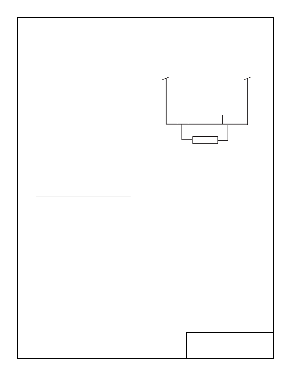
6.
Connect leads from the braking resistor to
drive terminals according to Figure 3 and Figure 4.
NOTE
External control components shown in Figure
5 are not supplied with the option. These
components are necessary for safe operation
of the Dynamic Braking option.
Figure 3. Lead Connections For Braking
Resistor (3% Duty Cycle)
B1/+
B2
BRAKING
RESISTOR
P
B
GPD 333