Yaskawa CM061 User Manual
Profibus-dp, Option kit cm061
Yaskawa Electric America, Inc –
www.yaskawa.com
IG.AFD.12, Page 1 of 4
Date: 11/17/06, Rev: 06-11
Profibus-DP
®
Option Kit
CM061
This document applies to the Yaskawa F7U, G7U, P7U, E7U, G5M(Spec F), and G5M(600V) drives. For
G5U(HHP) drives, refer to IG.G5HHP.12.
Unpack the CM061 Profibus-DP Option Kit and verify that all components are present and undamaged.
CM061 Option Kit Parts List
Qty.
Profibus-DP Option Card (SI-P1)
1
Installation Guide (IG.AFD.12)
1
Connect power to the drive and verify that the drive functions correctly. This includes running the drive from the operator keypad. Refer to the
appropriate drive technical manual for information on connecting and operating the drive.
Remove power from the drive and wait for the charge lamp to be completely extinguished. Wait at least five additional minutes for the drive to be
completely discharged. Measure the DC bus voltage and verify that it is at a safe level.
Remove the operator keypad and drive cover.
Remove the operator keypad and loosen any screws on the front of the
terminal cover. Simultaneously pushing the locking tabs on the bottom
right and left sides of the terminal cover inward, pull the bottom edge of
the terminal cover outward.
Loosen any screws on the front of the control cover. Simultaneously
pushing the locking tabs on the bottom right and left sides of the control
cover inward, pull the bottom edge of the control cover outward.
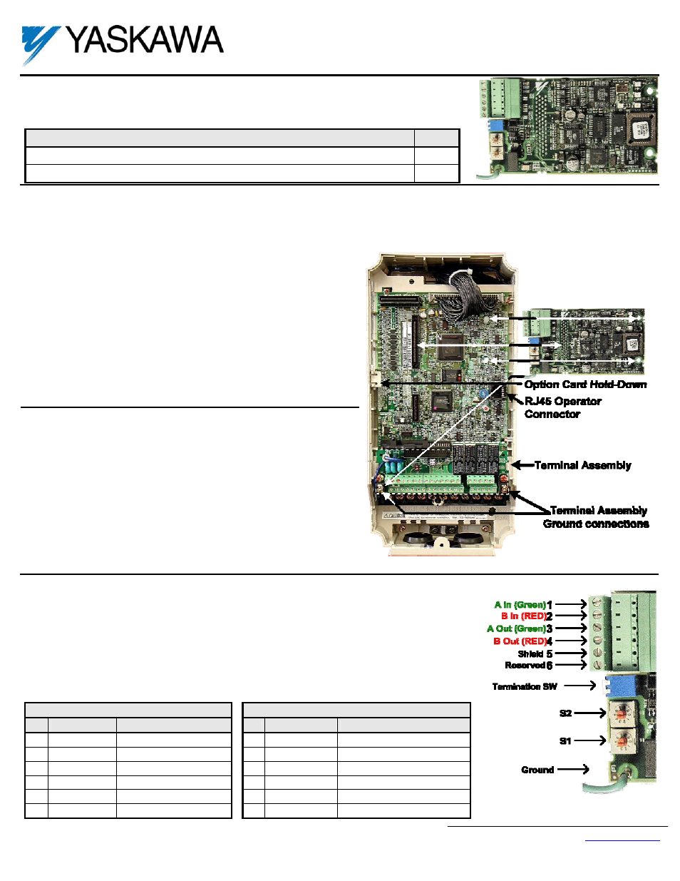
Remove the option card hold-down on the left side of the drive case by
carefully compressing the top and bottom until it becomes free of its
holder. Lift it out.
Mount the Profibus-DP Option Card on the drive.
Align the 2CN connector on the back of the Profibus-DP Option Card
with its mating J1 connector on the front of the drive control card.
Align the two standoffs on the front of the drive control board with the
two holes on the right side of the Profibus-DP Option Card.
Press the Profibus-DP Option Card firmly onto the drive 2CN connector
and standoffs until the J1 connector is fully seated and the drive
standoffs have locked into their appropriate holes.
Connect the Profibus-DP Option Card ground to a ground terminal on
the terminal assembly.
Connect the drive to the Profibus-DP communication network.
Connect the Profibus-DP network cable as shown in the figure to the right.
The cable shield must be contiguous between the beginning and end of any network segment. It is
recommended that the shield of the in cable and the out cable be twisted together. Do not connect the
shield to the shield connector, rather fold it back and secure it to the cable.
Use the pluggable connector that came with the Profibus-DP Option Card. The pluggable connector
contains a circuit board that remaps the terminal connections. Do not use an alternate connector.
Damage to the Profibus-DP Option Card and/or associated network devices could be damaged if an
alternate connector is used.
Plug Socket
Pin
Description
Definition
Pin
Description
Definition
1
A In (Green)
Negative
1
Reserved
No Connection
2
B In (Red)
Positive
2
Reserved No
Connection
3
A Out (Green)
Negative
3
A In/Out (Green)
Negative
4
B Out (Red)
Positive
4
B In/Out (Red)
Positive
5 Shield
Shield
5 Shield
Shield
6 Reserved
No
Connection
6 Reserved
No
Connection