Yaskawa CM048 User Manual
Option card cm048, Orks
Yaskawa Electric America, Inc. –
www.yaskawa.com
IG.AFD.20, Page 1 of 5
Date: 03/02/2012, Rev: 12-03
L
ON
W
ORKS
®
Option Card
CM048
Unpack the
L
ON
W
ORKS
Option Kit
and verify that all components are
present and undamaged.
Part
Qty.
LonWorks Option Card
(UTC000057)
1
Installation Guide (IG.AFD.20)
1
Verify that the drive is one of the following series: E7, P7, F7, or G7.
The
LonWorks Option Card
is only compatible with these drive series.
Apply power to the drive or panel and verify that they function correctly.
This includes running the drive through the drive keypad (or the door
mounted Bypass controls, in case of E7B, E7L, or P7B. Refer to the
appropriate technical manual for information on connections and
operation.
Remove power and wait for the drive charge lamp to be completely
extinguished. Measure and verify the drive’s DC BUS voltage to be at a
safe level.
Remove the operator keypad and drive cover(s).
Remove the operator keypad by depressing the tab on the right
side of the keypad and then pulling it out. In E7B, E7C, E7L, P7B,
P7C, or F7C, the keypad may already have been removed and
mounted on the enclosure door.
Remove the drive’s front cover until the entire control card is
exposed. The number of covers and the removal procedure varies
by drive series and capacity. Consult the drive’s technical manual
for details. In E7B, E7C, E7L, P7B, P7C, or F7C, the keypad may
already have been removed and mounted on the enclosure door.
Remove the option card hold-down plug on the left side of the
drive case by carefully compressing the top and bottom until it
becomes free of its holder and then pulling it out.
Mount the
L
ON
W
ORKS
Option Card
on the drive.
Align the 2CN connector on the back of the
LonWorks Option Card
with its mating 2CN connector on the front of the drive’s control board. Align
the two standoffs on the front of the drive’s control board with the two holes on the right side of the
L
ON
W
ORKS
Option Card.
Press
the
LonWorks Option Card
firmly onto the drive’s 2CN connector and standoffs until the 2CN connector is fully seated and the drive standoffs
have locked into their appropriate holes.
Standard Connection - Route the four wires from the
LonWorks Option Card
along the left side of the control board and connect them directly to the
R+, R-, S+ and S- terminals on the I/O terminal assembly as shown below.
E7L Connection - Route the four wires from the
LonWorks Option Card
to terminal board TB4 on the E7L control card. The E7L control board is
typically mounted on the left inside wall of the E7L enclosure. Connect the wires as shown below.
A noise free ground is essential for continuous, stable communications. DO NOT USE THE GROUND TERMINALS LOCATED ON THE DRIVE’S
TERMINAL BOARD OR CHASSIS. If an external, noise free ground is available, connect a ground wire from the ground terminal on the
LonWorks
option Card
to the ground. If no noise free ground is available, leave the ground terminal on the
LonWorks Option Card
un-terminated.
Standard Termination - Set the Termination Switch S1-1 to ON as shown below. This is independent of whether the drive is the first or last device on
the
LonWorks
network.
E7L Termination - Set the Termination Switch S1 to ON. This is independent of whether the drive is the first or last device on the
LonWorks
network.
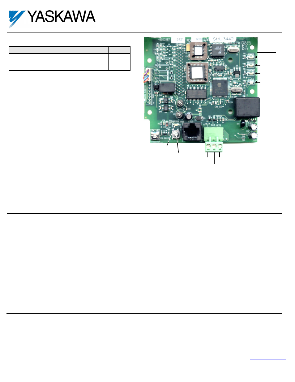
PWR
RECEIVE
TRANSMIT
FAULT
LEDs
net
A
net
B
shield
SERVICE
Button
SERVICE
LED
RJ45
Ground
Terminal