Yaskawa AI-14U User Manual
Analog input option card ai-14u
Yaskawa Electric America, Inc. – www.drives.com
IG.AFD.53, Page 1 of 3
Date: 07/01/04, Rev: 04-07
Analog Input Option Card
AI-14U
Part Number: AI-14U.
Applicability: F7, G7, GPD 515/G5, G5 HHP.
Note: If used in a GPD503/G3, refer to Instruction Sheet
02Y00025-0295.
Introduction: The AI-14U analog input option card is
mounted on the drive’s control board and enables the user to
interface one high-resolution (14-bit) analog speed reference.
This reference can be either voltage (0 to10VDC) or current (4
to 20mA). Frequency reference gain and bias are adjusted by
parameter settings in the drive. When installed, this card
replaces terminal 13 (GPD515/G5) or A1 (F7/G7) as the
primary analog speed reference location.
Receiving: All equipment is tested against defect at the
factory. Report any damages or shortages evident when the
equipment is received to the commercial carrier who
transported the equipment.
Warning: Hazardous voltage can cause severe injury or
death. Lock all power sources feeding the drive in the “OFF”
position.
Caution: This option card uses CMOS IC chips. Use proper
electrostatic discharge (ESD) protective procedures when
handling the card to prevent I.C. damage or erratic drive
operation.
Important:
1. If this option is being installed in a drive with an encoder (PG) feedback option card, that card will need to be temporarily
removed to allow access to connector 2CN on the drive’s control board and TC1 – TC3 on the AI-14U option card.
2. Before installing this option, a technically qualified individual, who is familiar with this type of equipment and the hazards
involved, should read this entire installation guide.
Installation and Wiring:
1. Disconnect all electrical power to the drive.
2. Remove the drive’s front cover.
3. Check that the “CHARGE” indicator lamp inside the
drive is off.
4. Use a voltmeter to verify that the voltage at the
incoming power terminals (L1, L2, L3) has been
disconnected.
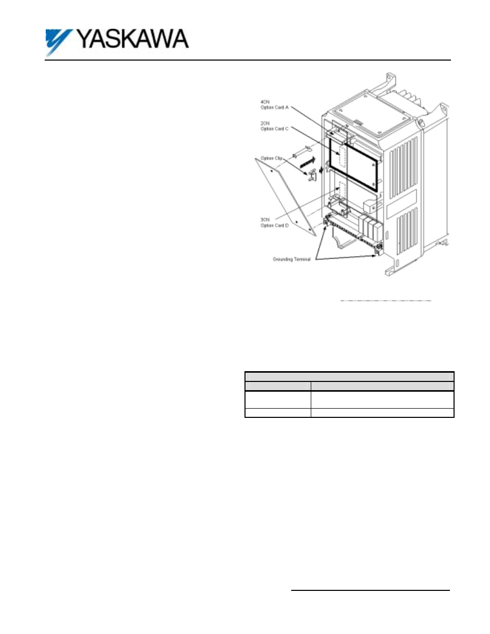
5. Option Card Installation: See Figure 1. Position the option card above the control board’s 2CN connector and gently
press the card into place.
6. Wiring: Refer to Figure 2 and Table 2. Make wire connections between the AI-14U card and the drive as well as all
peripheral devices. Observe the following:
a) Keep the AI-14U (i.e. control circuit) wiring separate from main circuit input/output wiring. A separate metallic
grounded conduit with only the option card’s wiring running through it is preferred.
b) To prevent erroneous operation caused by noise interference, use shielded cable for control signal
wiring. Limit the distance to 10m (33 feet) or less.
c) Route wires from the drive and connect to the peripheral device. Refer to the drive technical manual for further
information on use of shielded cable.
d) Important: Because the analog input is high-resolution, the voltage source accuracy of the analog input source must
be considered. To ensure accuracy, use a high-precision power supply for the voltage source.
7. Adjustment: There are no adjustments to be made on the AI-14U option; however, the drive will have to be programmed
for the input requirements of the remote device. Refer to Figure 3 and Table 3.
8. Reinstall and secure the drive’s front cover.
9. Place this instruction sheet with the drive’s technical manual.
Table 1. Specifications
Parameter
Value
Input Signal Level
0 to 10VDC (Input Impedance: 20K ohms)
4 to 20mA (Input Impedance: 250 ohms)
Input Resolution
14 bit (1/16,384)
Figure 1. AI-14U Option Card Installation