Analog input option card ai-14u – Yaskawa AI-14U User Manual
Page 2
Yaskawa Electric America, Inc. – www.drives.com
IG.AFD.53, Page 2 of 3
Date: 07/01/04, Rev: 04-07
Analog Input Option Card
AI-14U
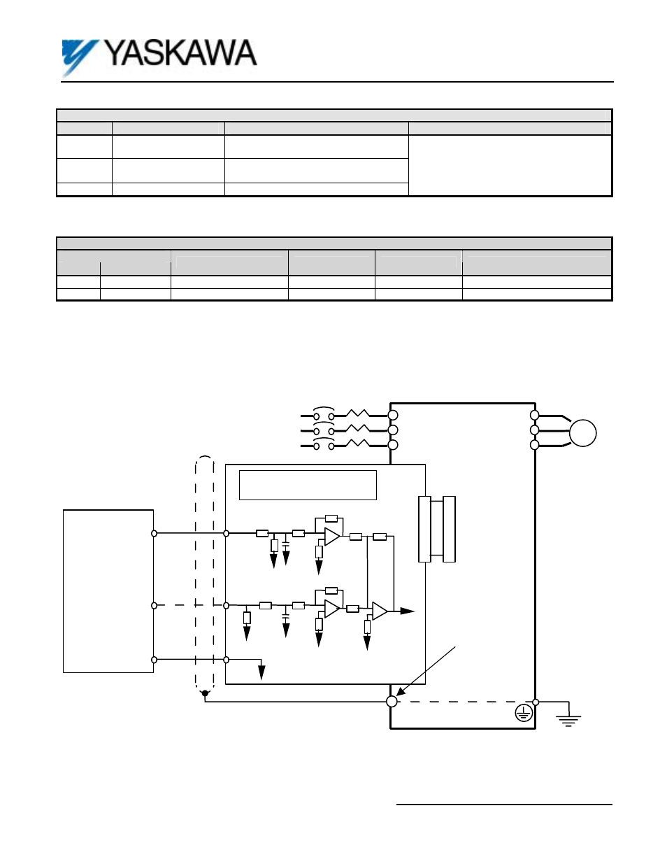
2CN
2CN
TC1
F7, G7,
GPD515/G5,
G5HHP
L1
L2
L3
T1
T2
T3
E
2uF
20K ohm
0V
I M
MOTOR
MCCB
SHIELD
0V
0-10VDC
4-20mA
0V
Analog Input
Source
*
*
Use High Accuracy Voltage Regulator
250 ohm
10K ohm
10K ohm
2uF
20K ohm
10K ohm
TC2
TC3
Grounding
Terminal:
F7, G7 = TB3
G5 = 12
AI-14U Card
Table 2. Terminal Functions of the AI-14U
Terminal
Function
Signal Level
Notes
TC1
Analog Voltage Input
Input Voltage: 0 to 10VDC
Input Impedance: 20kohms
TC2
Analog Current Input
Input Current: 4 to 20mA
Input Impedance: 250ohms
TC3 Signal
Common
0VDC
- Input Resolution: 1/16,384 (14 bit)
- Signal Linearity: +/-0.1%
- Terminal screws are metric size M3
Table 3. Adjustment of the Input Signals
Parameter
F7/G7
GPD 515/G5
Function
Setting Range
Increment
Factory Setting
H3-02 H3-02
Gain
0.0
to
1000.0%
0.1%
10VDC / 100.0%
H3-03
H3-03
Bias
-100 to 100%
1%
0%
Figure 2. AI-14U Interconnection Diagram