Yaskawa AI-040 User Manual
Isolated analog input option card ai-040
Yaskawa Electric America, Inc. – www.drives.com
IG.AFD.55, Page 1 of 4
Date: 10/07/05, Rev: 05-10
Isolated Analog Input Option Card
AI-040
Part Number: AI-040 Kit (UTC000015 Card) (formerly AI-14B2).
Applicability: F7, G7, GPD515/G5.
Note: If used in a GPD503/G3, refer to Instruction Sheet
02Y00025-0431.
Introduction: The AI-040 isolated analog input option board is
mounted on the drive’s control board and enables the user to
employ precision isolated analog signals to interface three
separate high resolution analog input signals, each of which may
be either current or voltage (13-bit + sign). These signals are
isolated from ground and the drive, but NOT from each other.
These signals can act as a direct replacement for the three
existing analog inputs available on the drive (3-channel individual
mode), or the signals can be added together and used as a
single frequency reference (3-channel addition mode). Gain and
bias are adjustable for both modes using drive parameters. The
polarity (sign) of the analog input can be used to control items
such as motor direction and torque direction.
Receiving: All equipment is tested against defect at the factory.
Report any damages or shortages evident when the equipment is
received to the commercial carrier who transported the
equipment.
Warning: Hazardous voltage can cause severe injury or death.
Lock all power sources feeding the drive in the “OFF” position.
Caution: This option card uses CMOS IC chips. Use proper
electrostatic discharge (ESD) protective procedures when
handling the card to prevent I.C. damage or erratic drive operation.
Important:
1. If this option is being installed in a drive with an encoder (PG) feedback option card, that card will need to be temporarily
removed to allow access to connector 2CN on the drive’s control board and TC1 – TC4 on the AI-040 option card.
2. Before installing this option, a technically qualified individual, who is familiar with this type of equipment and the hazards
involved, should read this entire installation guide.
Installation and Wiring:
1. Disconnect all electrical power to the drive.
2. Remove the drive’s front cover.
3. Check that the “CHARGE” indicator lamp inside the
drive is off.
4. Use a voltmeter to verify that the voltage at the
incoming power terminals (L1, L2, L3) has been
disconnected.
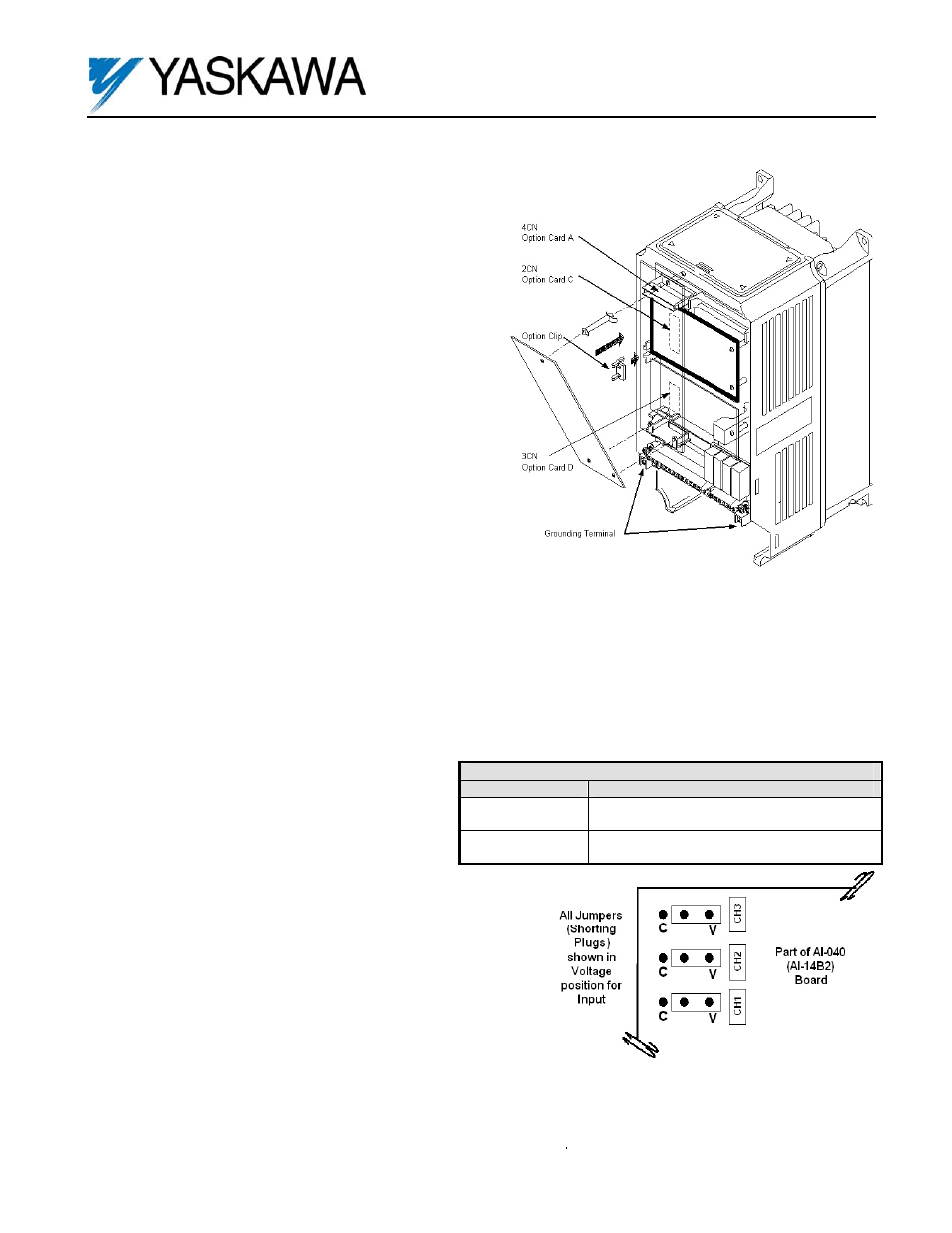
5. Option Card Installation: See Figure 1. Position the option card
above the control board’s 2CN connector and gently press the card
into place.
6. Wiring: Refer to Figure 3 and Tables 1 & 2. Make wire
connections between the AI-040 card and the drive as well as all
peripheral devices. Observe the following:
a) Determine whether a voltage or current signal will be used for
each of the channels of the AI-040 card. Set selection jumpers
accordingly. See Figure 2.
b) Keep the AI-040 (i.e. control circuit) wiring separate from main
circuit input/output wiring. A separate metallic grounded
conduit with only the option card’s wiring running through it is
preferred.
c) To prevent erroneous operation caused by noise interference,
use shielded cable for control signal wiring. Limit the distance to
10m (33 feet) or less.
Table 1. Specifications
Parameter
Value
Input Signal Level
0 to +/- 10VDC (Input Impedance: 20Kohms)
0 to 20mA (Input Impedance: 500ohms)
Input Resolution
Voltage: 13 bit (1/8192) + sign
Current: 1/6554
Figure 1. AI-040 Option Card installation
Figure 2. Voltage/Current Selection Jumpers