Yaskawa DO-02C User Manual
Digital output option card do-02c
Yaskawa Electric America, Inc. – www.drives.com
IG.AFD.57, Page 1 of 3
Date: 07/01/04, Rev: 04-07
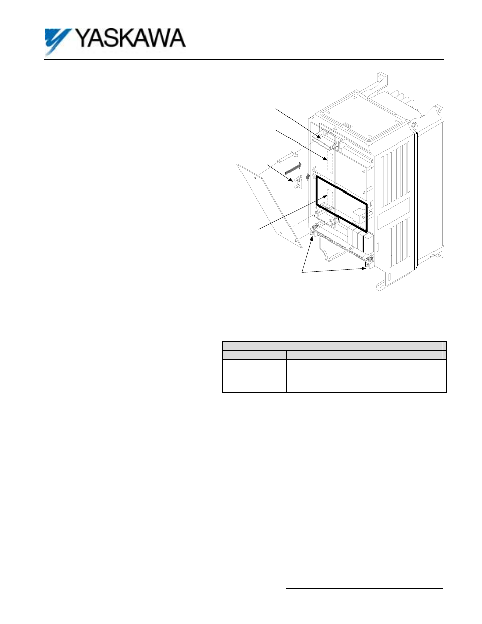
Digital Output Option Card
DO-02C
Grounding Terminal
4CN
Option Card A
2CN
Option Card C
3CN
Option Card D
Option Clip
Figure 1. DO-02C Option Card Installation
Part Number:
DO-02C.
Applicability:
F7, G7, GPD515/G5, G5HHP.
Introduction:
The Digital Output option board is mounted
on the drive’s control board. When installed, the DO-02C
option card provides the user with two sets of Form-C
relay contacts, the output from which is selected by the
programming of the drive’s parameters.
Receiving:
All equipment is tested against defect at the
factory. Report any damages or shortages evident when
the equipment is received to the commercial carrier who
transported the equipment.
Warning:
Hazardous voltage can cause severe injury or
death. Lock all power sources feeding the drive in the
“OFF” position.
Caution:
This option card uses CMOS IC chips. Use
proper electrostatic discharge (ESD) protective
procedures when handling the card to prevent I.C.
damage or erratic drive operation.
Important:
a) If this option is being installed in a drive with the
speed feedback option card, that card may need
to be temporarily removed to allow access to
connector 3CN on the drive’s control board and
terminal block TD on the option card.
b) Before installing this option, a technically
qualified individual, who is familiar with this type of equipment and the hazards involved, should read this entire
installation guide.
Installation and Wiring:
1. Disconnect all electrical power to drive.
2. Remove the drive front cover.
3. Check that the “CHARGE” indicator lamp inside
drive is off.
4. Use a voltmeter to verify voltage at incoming
power terminals (L1, L2, L3) has been
disconnected.
5. Option Card Installation: See Figure 1. Position the option card above the control board’s 3CN connector and gently
press the card into place.
6. Wiring: Refer to Figure 2 and Tables 2 and 3. Make wire connections between the DO-02C card and the drive as well as
all peripheral devices. Observe the following:
a) Keep DO-02C (i.e. control circuit) wiring separate from main circuit input/output wiring. A separate metallic grounded
conduit with only the option card’s wiring running through it is preferred.
b) To prevent erroneous operation caused by noise interference, use shielded cable for control signal wiring, and limit
the distance to 50m (165 feet) or less.
c) Refer to the drive technical manual for additional information on use of shielded cable.
7. Adjustment. None; however, drive parameters must be programmed. Parameter F5-01 controls terminals TD1-TD3 and
parameter F5-02 controls terminals TD4-TD6. See Table 4.
8. Reinstall and secure the drive’s front cover.
9. Place this instruction sheet with the drive’s technical manual.
Table 1. Specifications
Output Method
Available Outputs
Relay Contact
2 Channels (independent)
Form C (1A-1B)
250VAC, 1A or lower
30VDC, 1A or lower
Control voltage input (from drive): 24VDC (Isolated)