Digital input option card di-16h2 – Yaskawa DI-16H2 User Manual
Page 3
Yaskawa Electric America, Inc. – www.drives.com
IG.AFD.59, Page 3 of 4
Date: 07/01/04, Rev: 04-07
Digital Input Option Card
DI-16H2
Table 4. F3-01 Setting Unit and Range
F3-01 Set value
Setting Unit
Setting Range
0
BCD
1%
0 – 159%
1
BCD
0.1%
0 – 15.9%
2
BCD
0.01%
0 – 1.59%
3
BCD
1Hz
0 – 159Hz
4
BCD
0.1Hz
0 – 15.9Hz
5 or 6
BCD
0.01Hz
0 – 1.59Hz
7
Binary
65535 / 100%
0 – Maximum Output Frequency
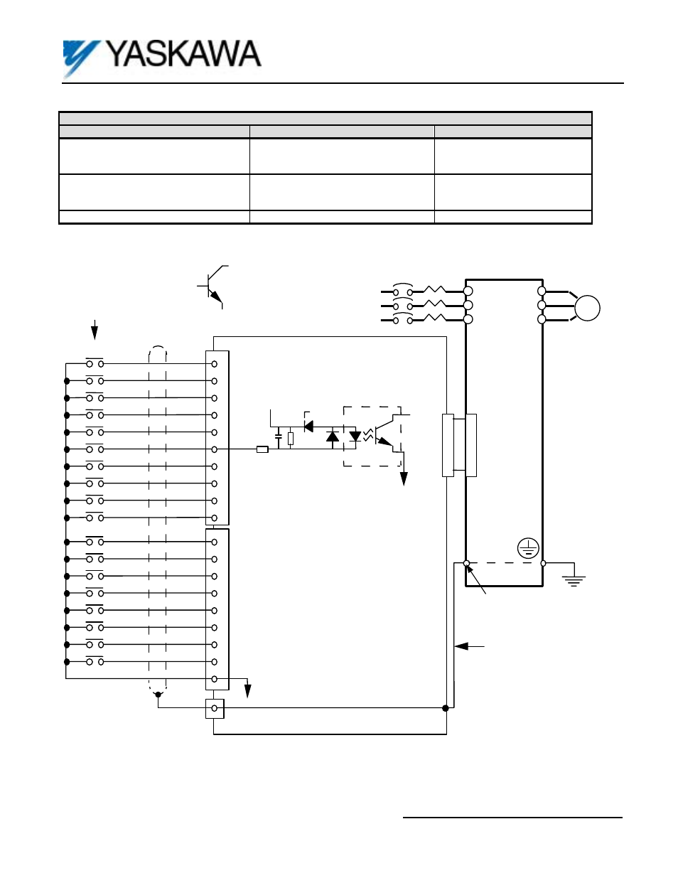
2CN
2CN
TC1
Grounding Terminal:
F7, G7: TB3
GPD 515/G5: 12
F7, G7,
GPD515/G5,
G5HHP
DI-16H2 CARD
L1
L2
L3
T1
T2
T3
D0
Open Collector
Transistor May Be
Used in Place of
Relay Contact
0.1uF
24K ohm
+24V
5.1K ohm
0V
6.2V
OPTICAL
ISOLATOR
I M
MOTOR
MCCB
SHIELD
OV
TYPICAL INPUT
CIRCUIT
(E)
1
2
3
4
5
6
10
7
8
9
1
2
3
4
5
6
7
8
9
TC2
TC3
D1
D2
D3
D4
D5
D6
D7
D8
D9
D10
D11
D12
D13
D14
D15
SIGN
SET
(E)
GROUNDING LEAD
WIRE (PART OF
DI-16H2 CARD)
Figure 3. DI-16H2 Interconnection Diagram