Digital input option card di-16h2 – Yaskawa DI-16H2 User Manual
Page 4
Yaskawa Electric America, Inc. – www.drives.com
IG.AFD.59, Page 4 of 4
Date: 07/01/04, Rev: 04-07
Digital Input Option Card
DI-16H2
Table 3. Terminal Functions of the DI-16H2
Function
Terminal Block
Pin
No.
Binary
Input
BCD Input
Notes
1 2
0
1
2 2
1
2
3 2
2
4
4 2
3
8
X 10
0
--- “On” when closed (shorted to 0VDC at TC2-9).
“Off when open.
5 2
4
1
6 2
5
2
7 2
6
4
8 2
7
8
X 10
1
--- Binary / BCD selection and input unit is set by drive
parameter F3-01; see Table 4.
--- Terminal screws are metric M3.
9 2
8
1
TC1
10 2
9
2
1 2
10
4
2 2
11
8
X 10
2
3 2
12
1
4 2
13
2
5 2
14
4
6 2
15
8
X 10
3
--- Set selection switch S1 according to the input signal
configuration being used.
S1
16
12
Binary 16 bits/BCD 4 digits
Binary 12 bits/BCD 3 digits
7 SIGN
Signal
--- SIGN signal: “Off” = Forward direction command
“On” = Reverse direction command
8
SET (load) Signal*
TC2
9 Common
(0VDC)
TC3
Shield Sheath Connection
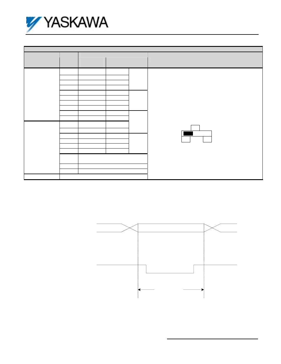
* SET (load) signal is used to tell the drive to read the data. To set, close between TC2-8 and TC2-9 by the timing shown in
Figure 4.
Digital Reference Data
(Terminals TC1-1 to -10,
TC2-1 t0 -6 and SIGN
signal, terminal TC2-7)
SET (load) signal
(Terminal TC2-8)
More
than
5ms
More
than
5ms
More than
40ms
Figure 4. Timing of Set (load) Input