Dual encoder feedback option card pg-w2 – Yaskawa PG-W2 User Manual
Page 3
Yaskawa Electric America, Inc. – www.drives.com
IG.AFD.61, Page 3 of 6
Date: 07/01/04, Rev: 04-07
Dual Encoder Feedback Option Card
PG-W2
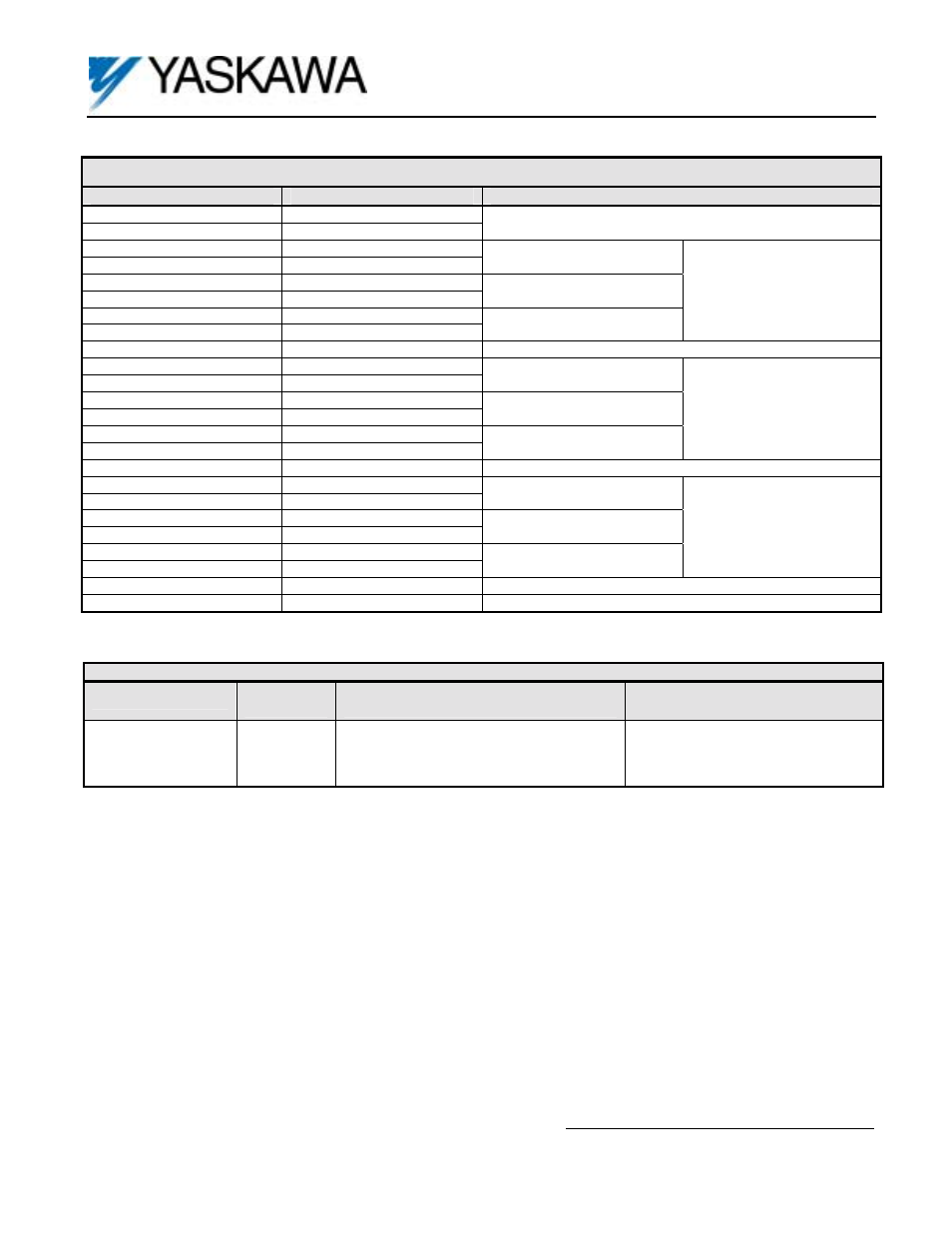
Table 1. Terminal Functions
Terminal Number
Terminal Description
Terminal Function
1 +12VDC
2 0VDC
Power Supply for Encoder (PG)
+12VDC, 200mA Maximum
3 A1+
4 A1-
A Channel
5 B1+
6 B1-
B Channel
7 Z1+
8 Z1-
Z (C) Channel
Encoder Input 1
Line Driver Signal Level
9
Shield
Shield Drain for Encoder Wiring. Same as Terminals 16, 23.
10 A2+
11 A2-
A Channel
12 B2+
13 B2-
B Channel
14 Z2+
15 Z2-
Z (C) Channel
Encoder Input 2
Line Driver Signal Level
16
Shield
Shield Drain for Encoder Wiring. Same as Terminals 9, 23.
17 AM+
18 AM-
A Channel
19 BM+
20 BM-
B Channel
21 ZM+
22 ZM-
Z (C) Channel
Pulse Monitor Output
RS-422 Signal Level
23
Shield
Shield Drain for Encoder Wiring. Same as Terminals 9, 16.
24
IG5
Pulse Monitor Terminals 17-22 Isolated Common
Table 2. Terminal and Wire Specifications
Terminal Symbol
Terminal
Screw
Clamping Torque
Lb-in (N-m)
Wire Range
AWG (mm
2
)
J1, J2
M2
1.8 to 2.2
(0.22 to 0.25)
26 to 16
(Stranded: 0.14 to 1)
(Solid: 0.14 to 1.5)