Dual encoder feedback option card pg-w2 – Yaskawa PG-W2 User Manual
Page 6
Yaskawa Electric America, Inc. – www.drives.com
IG.AFD.61, Page 6 of 6
Date: 07/01/04, Rev: 04-07
Dual Encoder Feedback Option Card
PG-W2
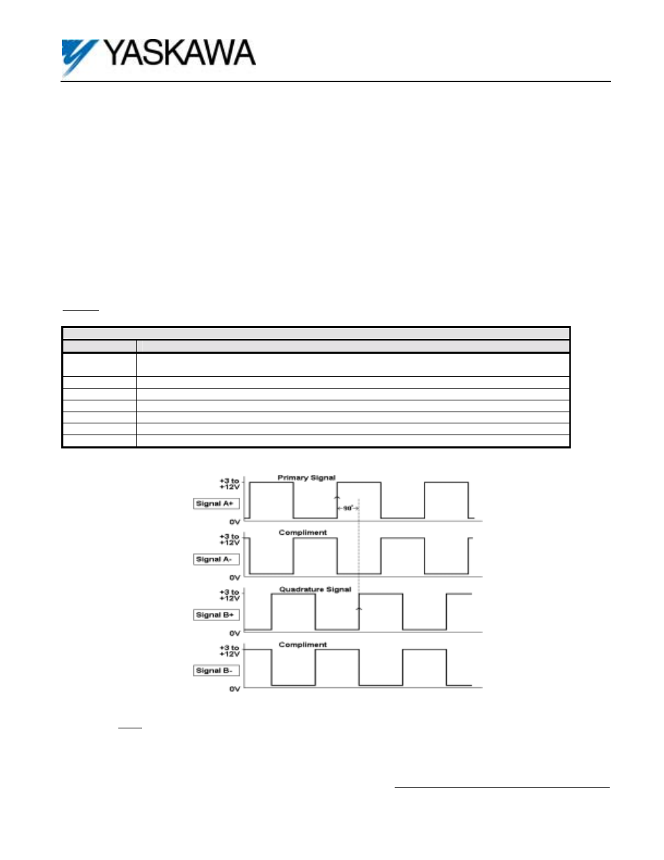
Figure 6. Encoder (PG) Signals – Forward Direction
16. Signal Type / Level Requirements: The PG-W2 card requires a “quadrature line driver with compliments” signal type
from the encoder (pulse generator). As shown in Figure 6, line driver signals include both a primary signal (Signal A+) and it’s
compliment (Signal A-). The compliment is the inverse of the primary signal. This scheme is used to improve the noise
immunity of the system. The encoder output signal voltage should be between +5VDC and +12VDC. An “open collector”
signal type WILL NOT work with the PG-W2 card.
A quadrature signal is one that lags the primary signal by 90 electrical degrees (1/2 of a pulse). The purpose of this is so that
the drive can detect the direction of the encoder rotation. As shown in Figure 6, for “forward” rotation of the encoder, signal A+
will lead signal B+ by 90
o
.
If any one of the four signals is missing, the drive cannot accurately measure the encoder rotation speed or direction.
17. Viewing Signals With An Oscilloscope: The PG-W2 option card has test points that can be used to connect an
oscilloscope. Figure 1 shows the locations of the test points on the PG-W2 card. Test points TP3 through TP8 are after the
compliment is subtracted out and the signals are buffered through the opto-isolators. See Figure 4. The voltage level on all
test points varies between 0 and +5VDC (TTL).
Caution: Always use an un-grounded oscilloscope so no noise is introduced into the common.
Table 3. PG-W2 Test Points
Test Point
Description
TP2
Although labeled GND, it is NOT earth ground. This test point should only be used in conjunction
with test points TP3 through TP8.
TP3
Input 1 Channel A (Terminals 3 & 4)
TP4
Input 1 Channel B (Terminals 5 & 6)
TP5
Input 1 Channel Z (Terminals 7 & 8)
TP6
Input 2 Channel A (Terminals 10 & 11)
TP7
Input 2 Channel B (Terminals 12 & 13)
TP8
Input 2 Channel Z (Terminals 14 & 15)
Note: All signals shown are in relation to power supply common, Terminal 2 of the PG-W2.