Yaskawa CM059 User Manual
Page 2
Yaskawa Electric America, Inc. –
www.yaskawa.com
IG.G5HHP.13 Page 2 of 10
Date: 11/06/06 Rev: 06-11
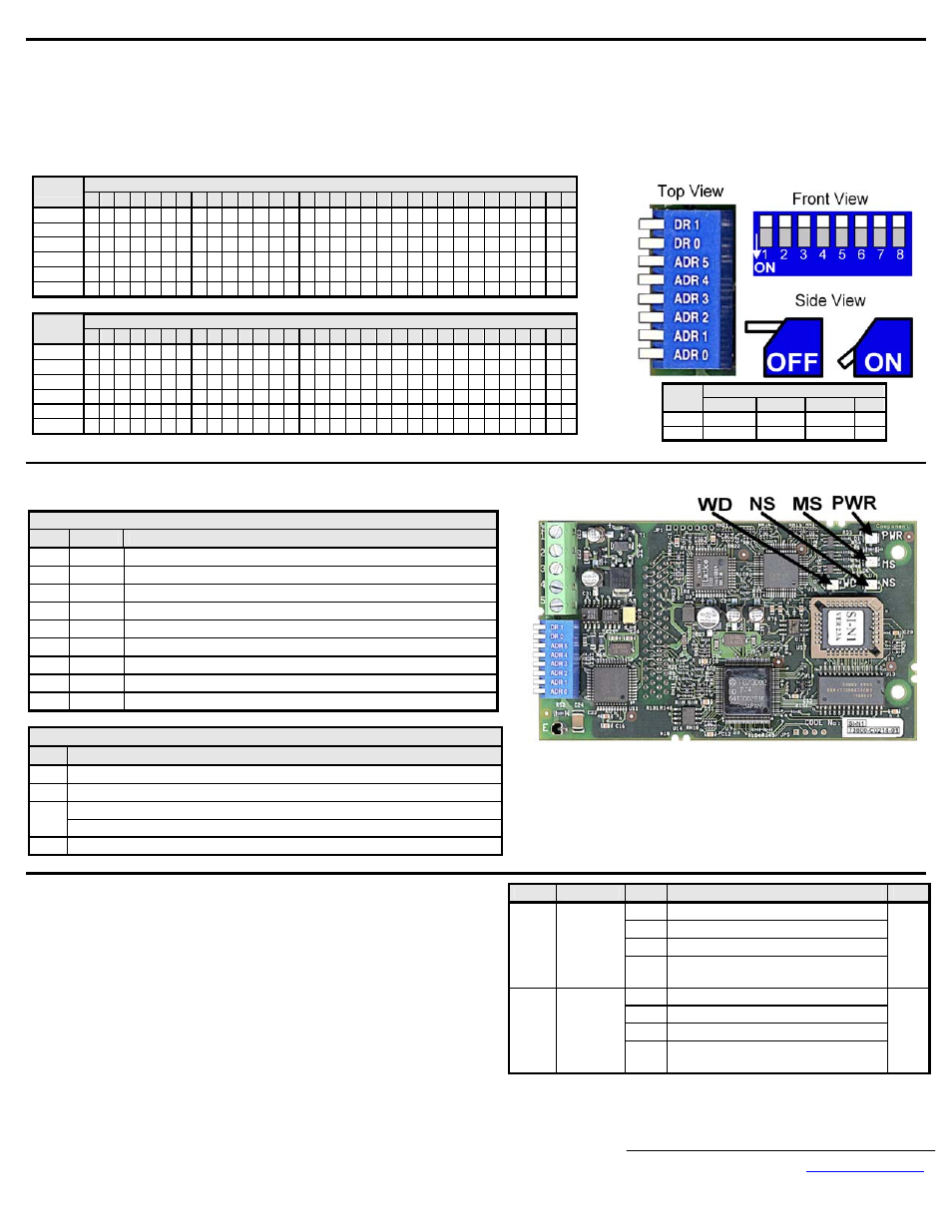
Set the CM059 DeviceNet Option Baud Rate
Set the Baud Rate for the CM059 DeviceNet Option to the network baud rate by setting DIP switches DR1 (1) and DR0 (2) as shown in the figure to the right. The baud rate
must match the baud rate of the DeviceNet master (PC/PLC/Scanner) in order for the connection to function properly.
Set the CM059 DeviceNet Option MAC ID
Set the MAC ID of CM059 DeviceNet Option by setting DIP switches ADR 5 (3) through ADR 0 (8) as shown in the table below. Each device on the network must have a
unique MAC ID, typically between 3 and 62. Addresses 0 and 1 are usually reserved for DeviceNet masters, address 2 for diagnostic/monitoring equipment and address 63
for vendor specific functions in some systems. Check the network schematic to verify the MAC ID setting.
MAC ID
Sw
00 01 02 03 04 05 06 07 08 09 10 11 12 13 14 15 16 17 18 19 20 21 22 23 24 25 26 27 28 29 30 31
ADR 5 (3) 0
0
0
0
0
0
0
0
0
0
0
0
0
0
0
0
0
0
0
0
0
0
0
0
0
0
0
0
0
0
0
0
ADR 4 (4) 0
0
0
0
0
0
0
0
0
0
0
0
0
0
0
0
1
1
1
1
1
1
1
1
1
1
1
1
1
1
1
1
ADR 3 (5) 0
0
0
0
0
0
0
0
1
1
1
1
1
1
1
1
0
0
0
0
0
0
0
0
1
1
1
1
1
1
1
1
ADR 2 (6) 0
0
0
0
1
1
1
1
0
0
0
0
1
1
1
1
0
0
0
0
1
1
1
1
0
0
0
0
1
1
1
1
ADR 1 (7) 0
0
1
1
0
0
1
1
0
0
1
1
0
0
1
1
0
0
1
1
0
0
1
1
0
0
1
1
0
0
1
1
ADR 0 (8) 0
1
0
1
0
1
0
1
0
1
0
1
0
1
0
1
0
1
0
1
0
1
0
1
0
1
0
1
0
1
0
1
MAC ID
Sw
32 33 34 35 36 37 38 39 40 41 42 43 44 45 46 47 48 49 50 51 52 53 54 55 56 57 58 59 60 61 62 63
ADR 5 (3) 1
1
1
1
1
1
1
1
1
1
1
1
1
1
1
1
1
1
1
1
1
1
1
1
1
1
1
1
1
1
1
1
ADR 4 (4) 0
0
0
0
0
0
0
0
0
0
0
0
0
0
0
0
1
1
1
1
1
1
1
1
1
1
1
1
1
1
1
1
ADR 3 (5) 0
0
0
0
0
0
0
0
1
1
1
1
1
1
1
1
0
0
0
0
0
0
0
0
1
1
1
1
1
1
1
1
ADR 2 (6) 0
0
0
0
1
1
1
1
0
0
0
0
1
1
1
1
0
0
0
0
1
1
1
1
0
0
0
0
1
1
1
1
ADR 1 (7) 0
0
1
1
0
0
1
1
0
0
1
1
0
0
1
1
0
0
1
1
0
0
1
1
0
0
1
1
0
0
1
1
ADR 0 (8) 0
1
0
1
0
1
0
1
0
1
0
1
0
1
0
1
0
1
0
1
0
1
0
1
0
1
0
1
0
1
0
1
Verify LED Status
Refer to the table on the following page for a complete listing of LED states.
LED Power-Up Sequence
LED
Color
Condition
PWR GREEN Steady
WD
RED
On for 0.25 sec
WD
NONE
Off for 0.25 sec
WD
GREEN Blink at 0.1ms interval
MS
GREEN On for 0.25 sec
MS
RED
On for 0.25 sec
MS
GREEN On for 0.25 sec
NS
GREEN On for 0.25 sec
NS
RED
On for 0.25 sec
LED normal operation Status
LED
Condition
PWR GREEN
MS GREEN
FLASH GREEN (no communication)
NS
REEN (communicating)
WD FLASH
GREEN
Remove power from the drive and wait for the charge lamp to be completely
extinguished. Wait at least five additional minutes for the drive to be completely
discharged. Measure the DC bus voltage and verify that it is at a safe level.
Reinstall all drive covers and the operator keypad.
Apply power to the drive and wait for the power-up sequence to complete.
Set parameters b1-01 and b1-02 to their appropriate values. Refer to the table to the
right for available b1-01 and b1-02 values.
Baud Rate
Sw
125kbps 250kbps
500kbps
N/A
DR1 (1)
0
0
1
1
DR0 (2)
0
1
0
1
Param
Function
Data
Description
Dflt
0 Digital
Operator
1 Terminals
2
Built-in Modbus RTU Terminals
b1-01
Reference
Source
Select
3
Option Card (CM059 DeviceNet
Option)
1
0 Digital
Operator
1 Terminals
2
Built-in Modbus RTU Terminals
b1-02
Run
Command
Source
Select
3
Option Card (CM059 DeviceNet
Option)
1