Yaskawa SGTA-LSKNNC Sensor Kit User Manual
Detail a
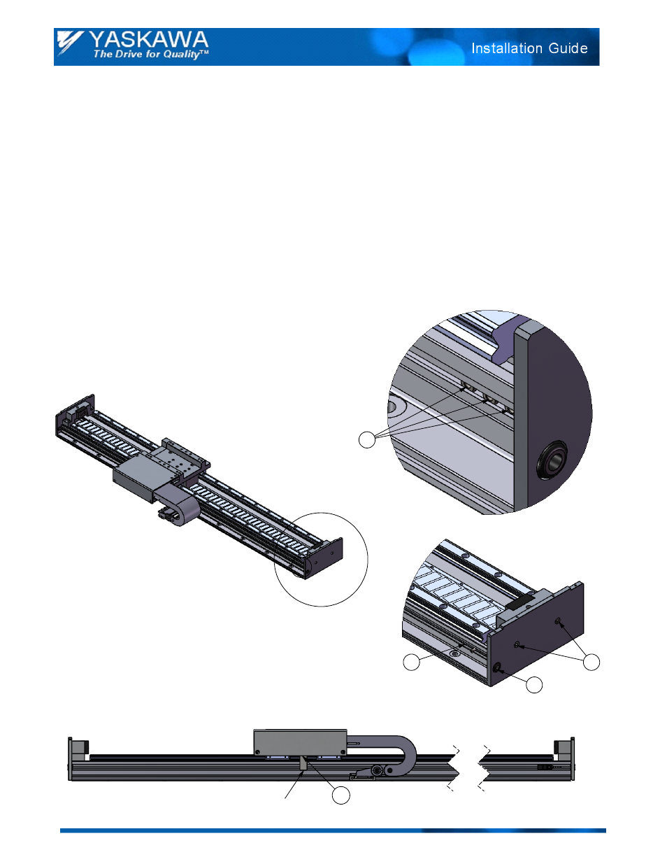
A
B
1
5
Sensor Target
DETAIL B
2
3
6
Sensor Kit Installation Guide
Part Numbers: SGTA-LSKNNC, SGTA-LSKNNO, SGTA-LSKPNO
Assembly Instructions:
Locate the 3 - M3 locknuts in the sensor T-slot.
1.
Fasten sensor to locknut with the M3 flat head socket cap screw, provided in kit. Position sensor along T-
2.
slot and tighten. Repeat for additonal sensors, if applicable.
Thread sensor cable through grommet located in endplate. Sensor cable not shown.
3.
Follow sensor manufacturer's instructions for wiring. Manufacturer's instructions included in kit.
4.
Apply power to the sensors and confirm successful operation. When the Sensor Target (shown below)
5.
passes over the sensor, a red LED on the sensor should turn on. If not, the distance between the target
and sensor may need to be adjusted. Adjust the spacing by loosening the 2 - M3x6 standard head socket
cap screws holding the Sensor Target to the carriage. Tighten the screws once adjustment is complete.
Remove unused locknuts (not required). First remove endplate by removing the 2 - M4x10 button head
6.
socket cap screws, and then remove the unused locknuts. Reattach endplate using the 2 - M4x10 button
head socket cap screws.
Doc#: IG.SigmaTracSGT.02 Yaskawa America, Inc.2010 www.yaskawa.com June 29, 2010 1/2
DETAIL A