Sheet1(2), Drawing view19, Drawing view21 – Yaskawa SGTA-LSKNNC Sensor Kit User Manual
Page 2: Drawing view23, Cover kit installation guide
4
3
5
5
2
1
9
9
9
6
8
7
7
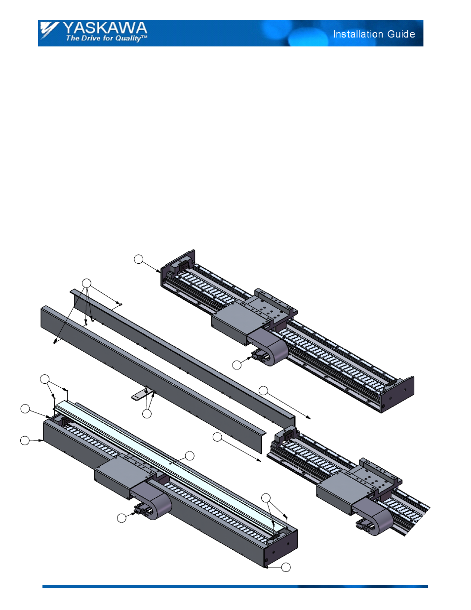
Cover Kit Installation Guide
Part Numbers: SGTA-CVR3-ooo, SGTA-CVR4-ooo, SGTA-CVR9-ooo, SGTA-CVRA-ooo
Assembly Instructions
Remove endplate by removing the 2 - M4x10 button head socket cap screws.
1.
Remove lower metal bracket ("L" shaped bracket). Cut cable tie-wraps if needed to gain access and
2.
remove the 2 - M6x8 button head socket cap screws. Also remove the 2 - M3x8 button head socket
cap screws holding metal bracket to base. Then slide out the M3 locknuts from the lower T-slot on the
base.
Use the longer M3x12 button head socket cap screws, provided in kit, to attach the metal bracket to the
3.
center of the side cover (attach to one side cover only). Add M3 locknuts to the screws and hand-
tighten. M3 locknuts provided in kit.
Insert M3 x 8 button head socket cap screw, provided in kit, into side cover. Add M3 locknut and hand-
4.
tighten. Repeat for all remaining holes on the side covers.
Slide side covers onto base by inserting locknuts into lower T-slots on base.
5.
Reinstall endplate using the 2 - M4x10 button head socket cap screws from step #1.
6.
Align end of side covers with endplates and tighten all screws from steps #3 and #4.
7.
Reinstall plastic cable carrier mounting bracket to metal bracket using the 2 - M6x8 button head socket
8.
cap screws from step #2. Tie-wrap cables to mounting bracket. Tie-wraps provided in kit.
Set top cover across both endplates and fasten with 4 - M3x8 button head socket cap screws, provided
9.
in kit.
Doc#: IG.SigmaTracSGT.02 Yaskawa America, Inc.2010 www.yaskawa.com June 29, 2010 2/2