Table 6 – Yaskawa CDBR-xxxB User Manual
Page 6
1 Replacing CDBR Spec. B and C with CDBR Spec. D
6
YASKAWA PL.CDBR.01 CDBR - Product Transition Guide
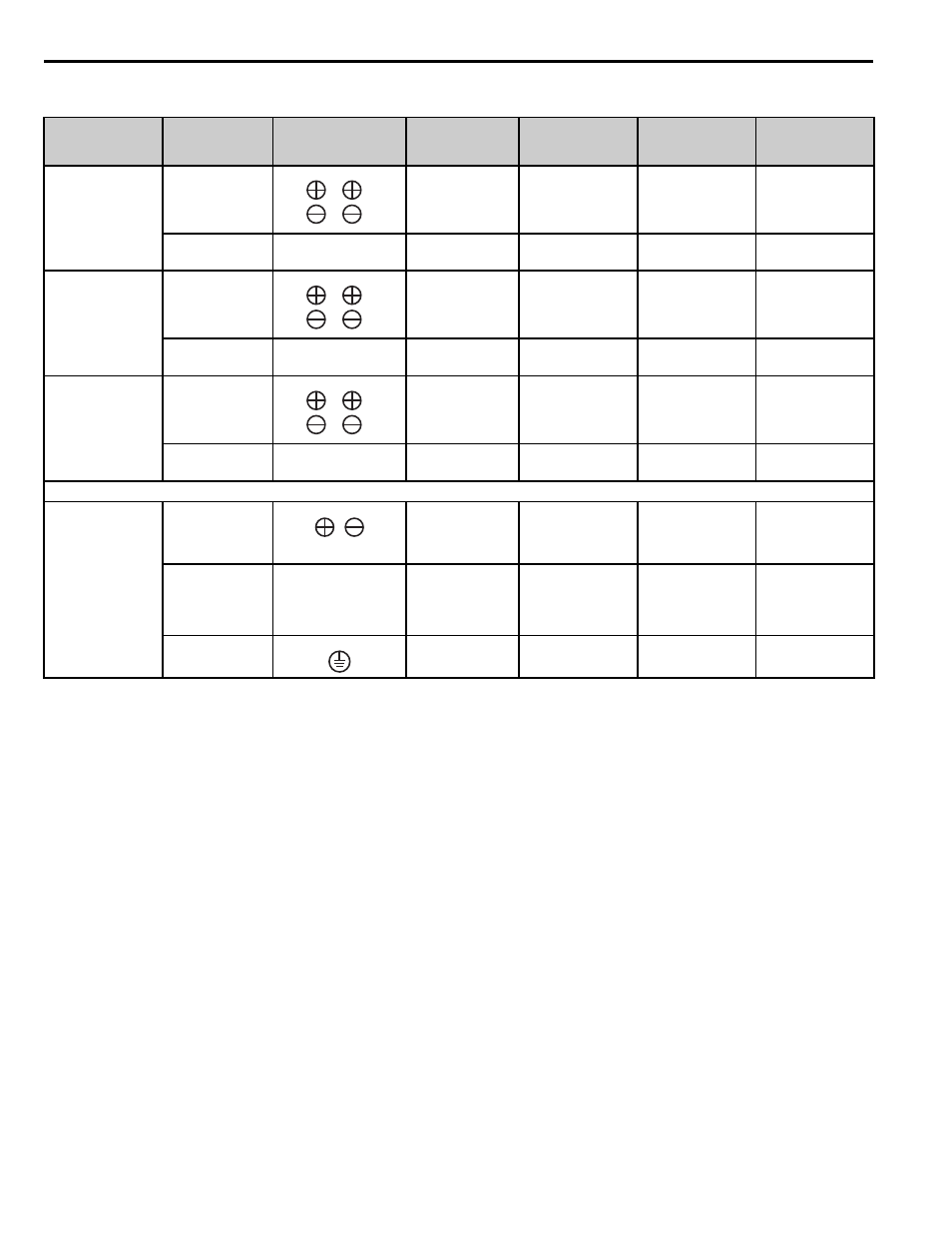
Table 6 Wire Gauges and Torque Specifications
Model
CDBR-
Circuit
Terminal No.
Screw Size
Tightening
Torque
N.m (lb-in)
Applicable
Gauge mm
2
(AWG)
Recomm. Gauge
mm
2
(AWG)
2015B
2022B
4030B
4045B
5037B
Main Circuit
M4
1.50 (13.3)
3.5-5.5
(12-10)
-
Control Circuit
1 2 3
4 5 6
M4
2.45 (21.7)
0.75-2
(18-14)
-
2045B
4090B
5110B
Main Circuit
M5
2.45 (21.7)
5.5-8
(10-8)
-
Control Circuit
1 2 3
4 5 6
M4
1.76 (15.6)
0.75-2
(18-14)
-
2110B
4220B
5300B
Main Circuit
M6
4.90 (43.4)
22 (4)
8-14 (8-6)
<1> CDBR- C model also available.
<2> Models CDBR-5037B, 5110B, and 5300B can reach an operating voltage of 1040 Vdc. Select wire that is suitable for the operating voltage.
<3> For 8-6 (8-14) wire size, use UL 1283 heat resistant vinyl insulated copper wire or equivalent.
-
Control Circuit
1 2 3
4 5 6
M4
1.76 (15.6)
0.75-2
(18-14)
-
The terminal sizes and positions of the new CDBR braking unit are not directly compatible with previous models.
2037D
4045D
5037D
Main Circuit
B1, B2
M5
2.7-3.0
(23.9-26.6)
5.5-8
(10-8)
5.5
Control Circuit
IN1, IN2
OUT1, OUT2
SB, SC, MA, MB, MC
EA, EB, EC
M3.5
0.8-1.0
(7.1-8.9)
0.75-2
(18-14)
0.75
Main Circuit
M5
2-2.5
(17.7-22.1)
8 (8)
8
0
0
0
0
0
0
,