Yaskawa MicroTrac Gateway to Allen-Bradley Data Highway Plus for use with Microtrac LAN User Manual
Page 3
Introduction
3
Drive Description
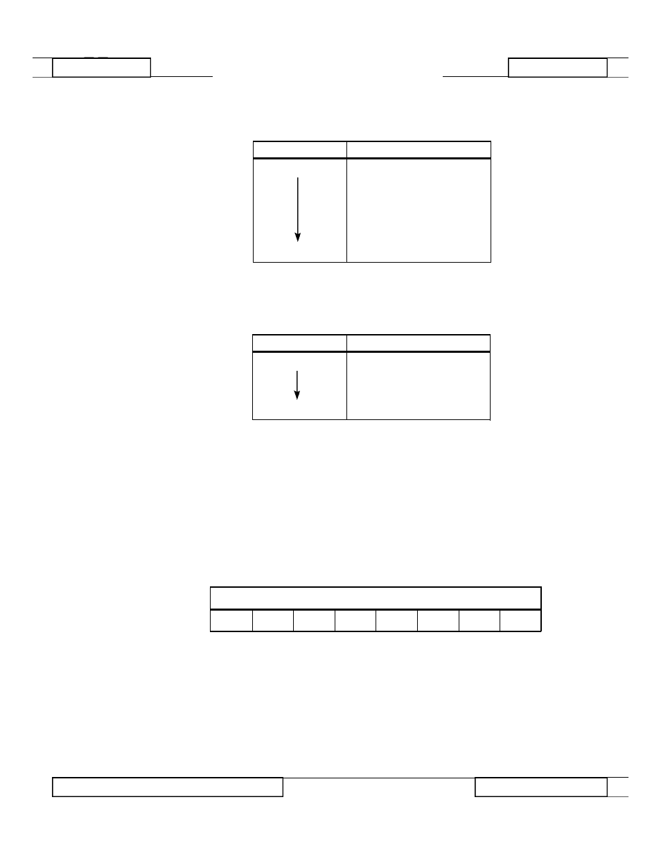
Install jumper plugs on E1 as shown in Table 1:
Install jumper plugs on E4 as shown in Table 2:
No jumpers are installed on E3.
The node ID is set using the 8-position DIP switch, SW1. Enter the binary node
ID by choosing either a "0" or "1" for each bit. The least significant bit (LSB)
and the most significant bit (MSB) positions are labeled on the board. The LSB
is toward the top of the board. Leaving the switch in the down position sets the
switch at "0". For example, node ID 200, represented in binary form as 11 0 0
1000, is set as shown in Table 3:
2
HARDWARE
MicroTrac Network Interface Card
M i c r o Tr a c
N e t w o r k
Interface Card
Table 1. E1 Settings
POSITION
JUMPER
TOP
YES
YES
NO
NO
NO
YES
NO
BOTTOM
YES
Table 2. E4 Settings
POSITION
JUMPER
IRQ2
NO
YES
NO
NO
IRQ7
NO
Table 3. Network Interface Card DIP Switch SW1 Settings
MSB
LSB
UP
UP
DN
DN
UP
DN
DN
DN
RD 906-20
© 1994 MagneTek, Inc.
94-04