Yaskawa Microtrac Gateway to Square D Sy/MAX Family of PLCs for use with Microtrac LAN User Manual
Page 6
6
PAC output channels numbered 1 to 255 to the “interfaced” PLC registers
numbered from 3501 to 3755).
The PLC gateway does not allow the mixing of data types for a single PLC
register (i.e., a single PLC register may not contain both logic and numeric
information). Also, a single PLC register may not be assigned to different
kinds of PAC blocks (i.e., a single register may not be assigned to a PAC
NUMI and to a PAC RDCI). However, a single register may be assigned to
multiple PAC NUMIs or to multiple PAC LOGIs.
The following rules MUST be followed (specifically, these steps increase the
efficiency of communication, and reduce communication overhead):
1.
The PLC registers assigned to PAC outputs MUST be within a group
of consecutive numbers.
2.
The range of PLC registers assigned to PAC outputs MUST not
contain any PLC registers assigned to PAC inputs.
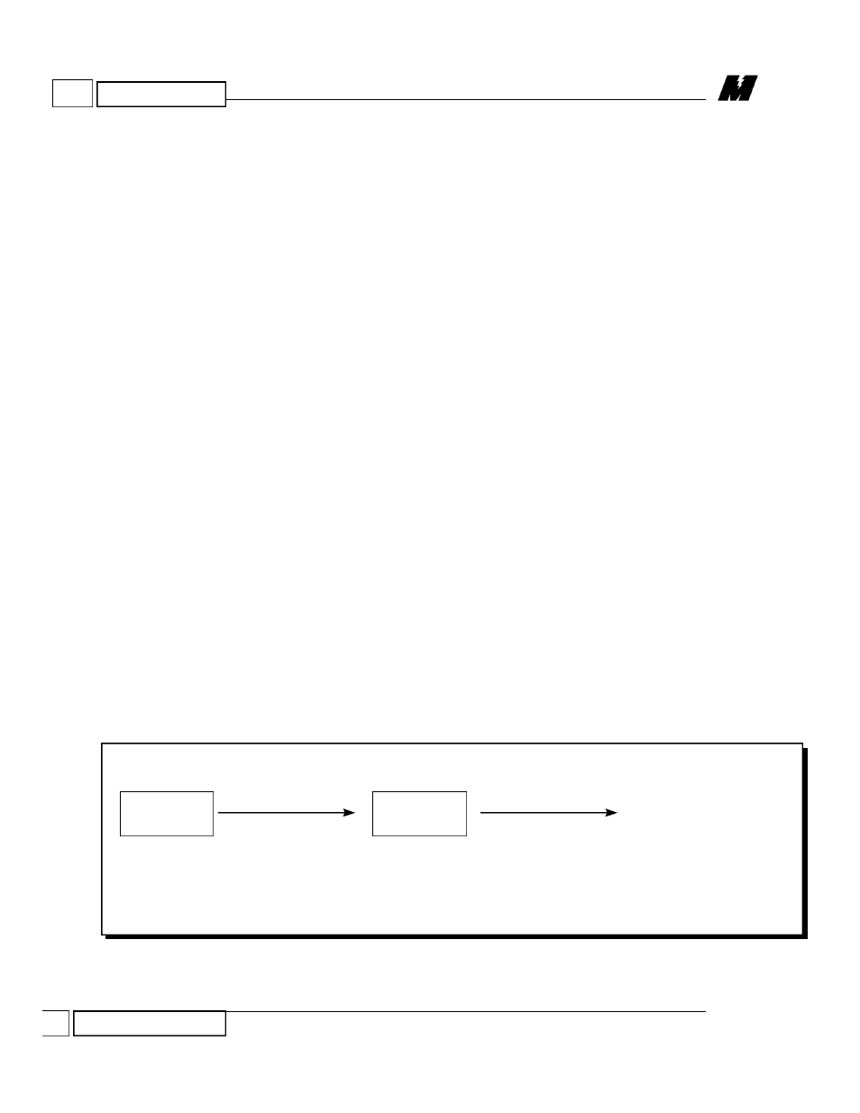
Logic Outputs (LOGO) from a PAC schematic to a PLC is illustrated in
Figure 1.
Each PAC block requires a node number, a channel number, and a subchannel
number.
The node number will usually be 200.
The channel number will be in decimal notation. The associated interfaced
PLC register is the PAC channel number plus 3500. For example:
Channel 10 = Register 3510
Channel 27 = Register 3527
4
OPERATION
Logic (I/O) Data
5/2/95
Logic (I/O) Data
Figure 1.
PAC to PLC Logic Output
PAC BLOCK
PLC GATEWAY
PLC LADDER LOGIC
LOGO
WRITE
ARCNET
CABLE
SY/LINK
COMM CABLE
3510
---
I I
---
-03
NODE: 200
CHAN: 10
SUB: 3
RD 914-10