Yaskawa Microtrac Gateway to Square D Sy/MAX Family of PLCs for use with Microtrac LAN User Manual
Page 8
8
4/12/94
4
OPERATION
Numeric (I/O) Data
Numeric (I/O)
Data
The subchannel number also will be in decimal, and will directly correspond to
the bit number of the PLC output. Thus, the 16 possible bits are as follows:
Subchannel 1 = Bit 1
Subchannel 2 = Bit 2
Subchannel 15 = Bit 15
Subchannel 16 = Bit 16
Any drive can request logic inputs (LOGI) from any register and bit of the
PLC that has outputs defined for that location. The MicroTrac DSD Kernel
will select the appropriate bit and send it to the appropriate LOGI block.
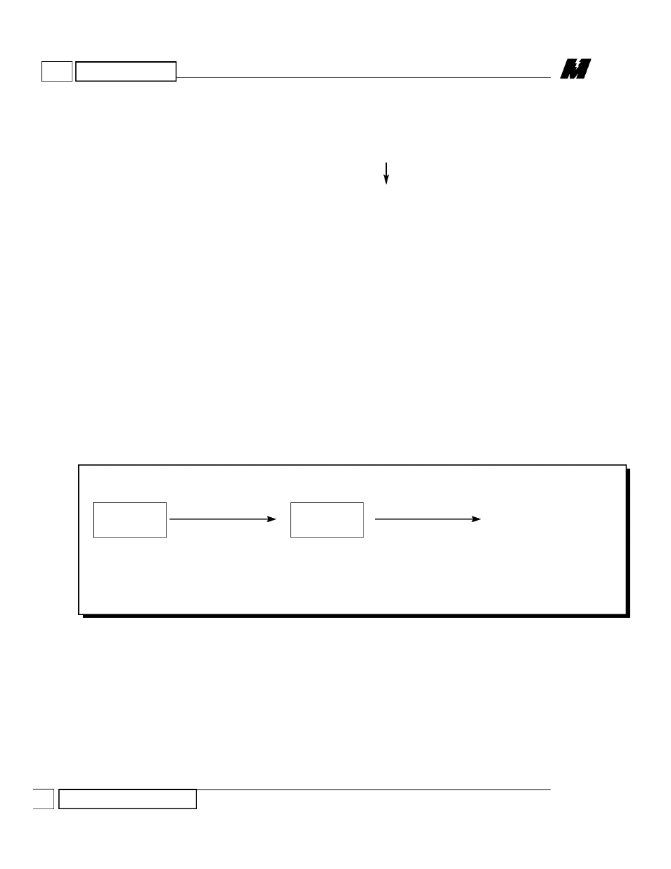
Numeric Outputs (NUMO) from a PAC schematic to a PLC is illustrated in
Figure 3.
Each PAC block requires a node number and a channel number.
The node number will usually be 200.
The channel number will be in decimal notation. The associated interfaced
PLC register is the PAC channel number plus 3500. For example:
Channel 10 = Register 3510
Channel 27 = Register 3527
No subchannel number is required.
A decimal point location parameter is required.
Figure 3.
PAC to PLC Numeric Output
PAC BLOCK
PLC GATEWAY
PLC LADDER LOGIC
NUMO
WRITE
ARCNET
CABLE
SY/LINK
COMM CABLE
3512
NODE: 200
CHAN: 12
RD 914-10