Front panel description – Yaskawa SMCGUI-THK1 User Manual
Page 26
22
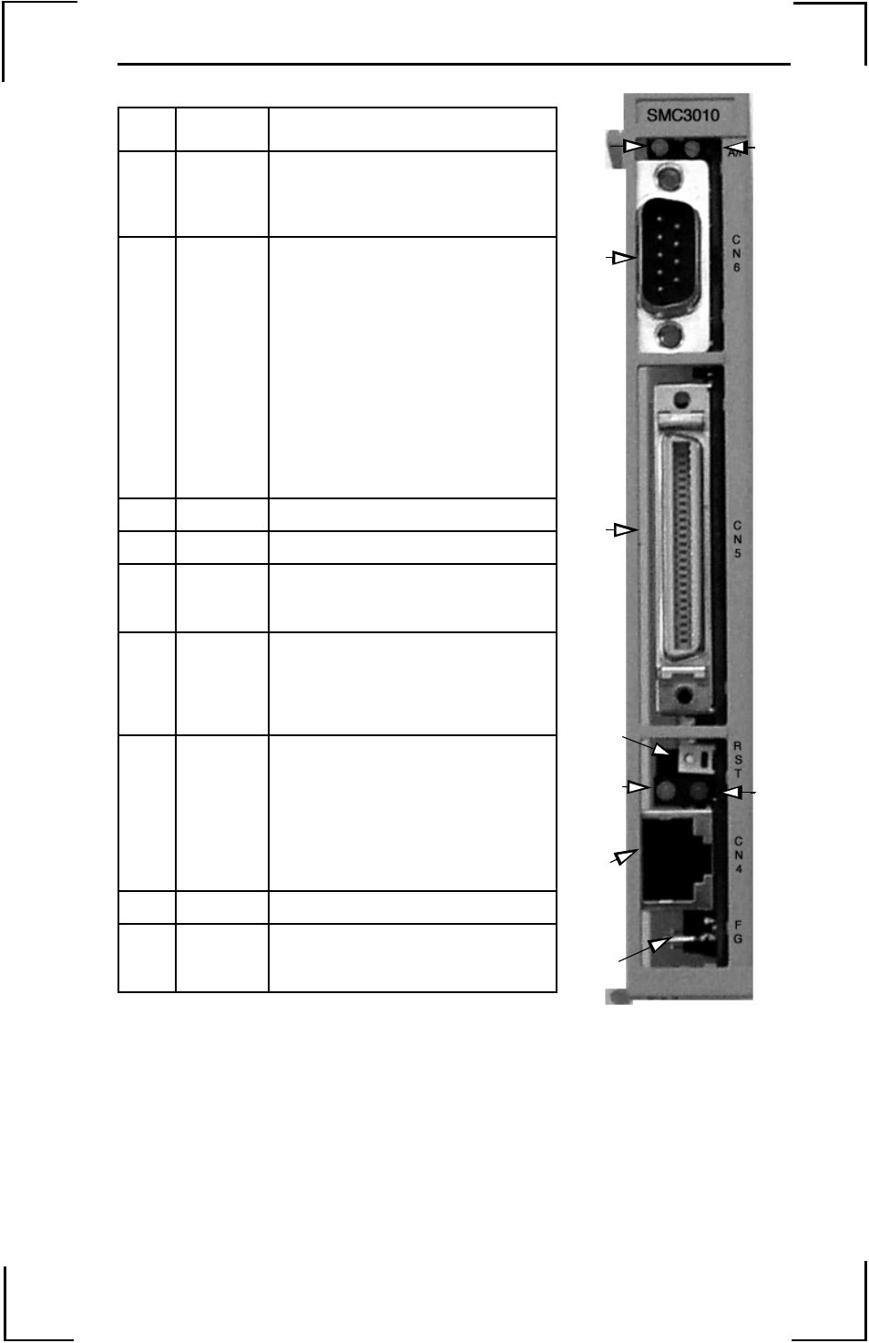
Front Panel Description
No.
Name
Description
(1)
Power
ON
A lit green LED indicates that the
+5 VDC power supplied to the
LEGEND-MC controller from the
LEGEND amplifier is working.
(2)
Alarm/
Error
A red LED that will flash on initially at
power-up and stay lit for approximately
1-8 seconds. After power-up, the LED
will illuminate for the following
reasons:
Position error occurs when the
measured value is greater than the
position error limit setpoint. Manual
reset of the controller, noise and/or a
failure in the processor can also
trigger this alarm for a short time. If
the error does not clear, please
contact your local Yaskawa
representative for assistance.
(3)
CN6
9 pin male D-Sub serial port connector
(4)
CN5
3M 50 pin high density I/O connector
(5)
RST
Reset switch. Causes the controller to
reboot, and load the application
program and parameters from flash.
(6)
Ethernet
status
A green LED that is lit when there is an
Ethernet connection to the controller.
This LED tests only for the physical
connection, not for an active or
enabled link.
(7)
Ethernet
status
The yellow LED indicates traffic across
the Ethernet connection. This LED will
show both transmit and receive activity
across the connection. If there is no
Ethernet connection or IP address
assigned, the LED will flash at regular
intervals to show that the BOOTP
packets are being broadcast.
(8)
CN4
10 BaseT Ethernet RJ485 Connector
(9)
FG
Frame ground spade terminal.
Connect to ground terminal on
LEGEND Amplifier
(1)
(2)
(3)
(4)
(5)
(7)
(6)
(8)
(9)