Yaskawa SmartTrac Ethernet Card User Manual
Page 14
SMART TRAC Ethernet Card
12
••
Contents Technical Manual Smart Trac Ethernet Card
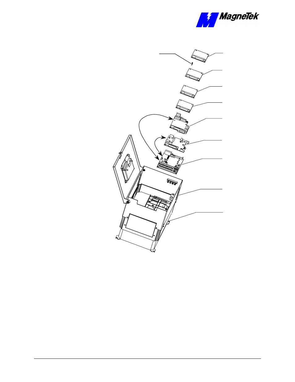
2CN
Connector
4CN
Connector
CPU Card
PG Card
PS Card
Ethernet
Card
Adapter
Ring
Optional
PC/104
Card
Card
PC/104
Optional
Smart Trac
Smart Trac
Smart Trac
Smart Trac
Card
Inverter Control
Main Chassis
Standoffs (4
places on top of
each card)
Figure 4. Smart Trac Ethernet Card Stack Position
1. To install the Ethernet card, orient the pins on the card at ZJ1 and ZJ2
with the female pin connector on the card below it (the PS Card).
Gently but firmly push the Smart Trac Ethernet card onto the card
below it. Make sure connecting pins are in alignment before pushing
the two boards tightly together. Secure the card using four (4) metal
standoffs.
2. Replace all other cards, securing each with four (4) metal standoffs and
the reverse of steps in "Appendix D – Removing the Smart Trac Card
Stack".