Yaskawa V7 Large HP User Manual
Page 2
Date: 07/01/04, Rev: 04-07
Page 2 of 5
TM.V7SW.032H
Background and Application Information:
Traditional fiber winding uses one of several methods to control traverse motor speed: Classical
precision winding, random winding, or pattern jump (also referred to as ribbon breaking).
In classical precision winding, the spindle and traverse motors are kept at a constant ratio, usually by
mechanical gearing. This ratio is typically on the order of about three decimal places because more
common ratios (integer or sub-integer) cause multiple wraps of thread to lay on top of each other, forming
what is known as a “ribbon” defect. Classical precision winding produces the highest quality package, but
has several drawbacks. Winders employing this technique cannot operate at high speeds due to
mechanical limitations of the traverse guide. Also, these systems require several different stages of
belting to achieve the unusual gear ratios, resulting in increased mechanical complexity.
Random winding permits much higher speeds because the traverse motor speed is held constant. Since
the spindle motor speed is constantly changing the laying of the fibers appears random. However, the
resulting package is not as dense as a precision wound package and tends to form ribbons.
Pattern jump, or ribbon breaking, has the high speed benefits of random winding but produces a higher
quality package. This method oscillates the traverse motor speed in a sawtooth fashion such that the
motor speed will only briefly pass through “bad” ratio areas as the package diameter builds, reducing the
number of ribbons. This is the method used in Yaskawa “P-jump” or “traverse” software.
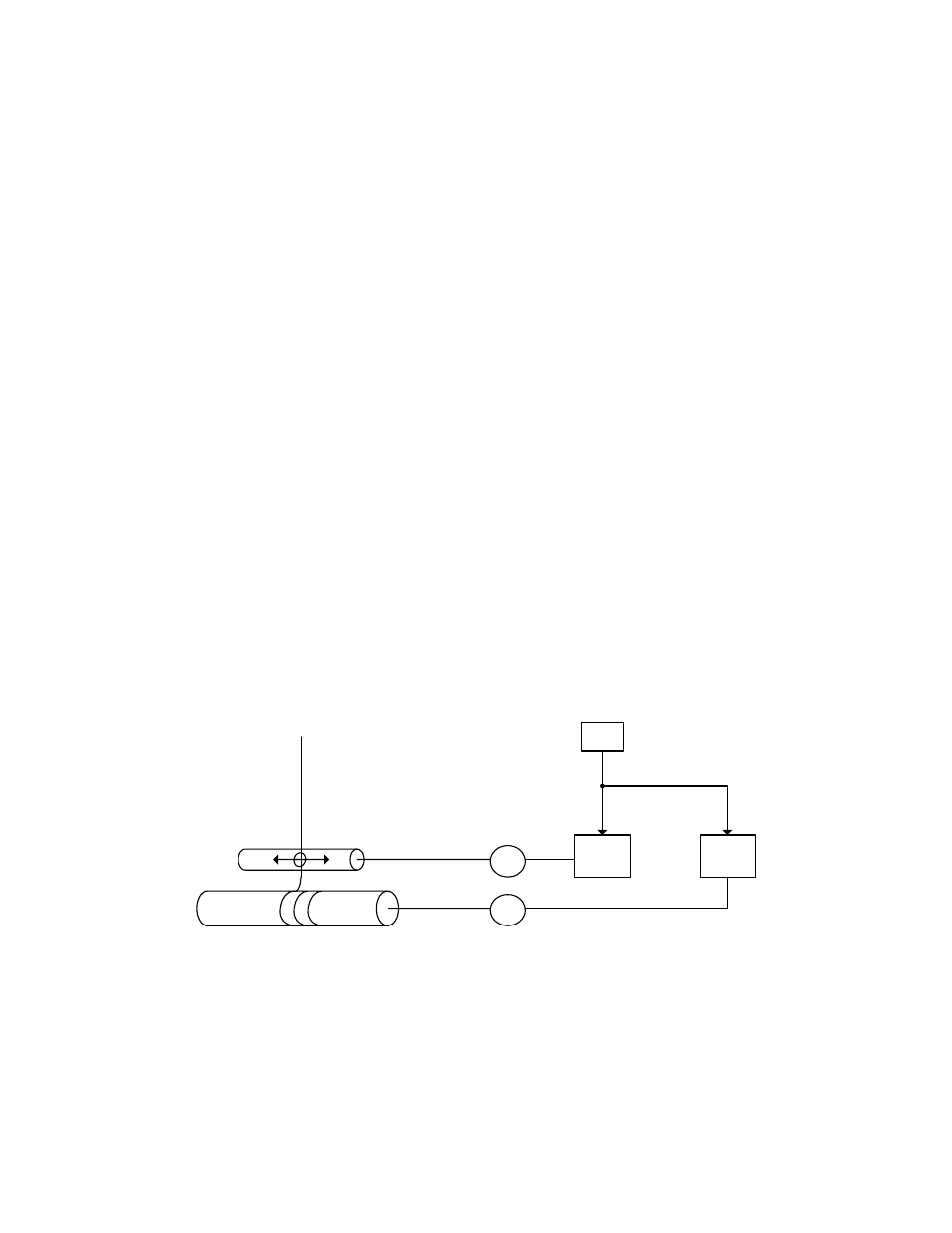
The “winder ratio” feature of this software is designed to electronically control the the spindle and traverse
drive output frequencies to run at a precise ratio. A PLC writes the frequency reference to both drives
simultaneously via a Memobus broadcast command. Two parameters (changeable during run) are
provided to ratio this speed reference. The PLC changes the traverse drive ratio parameters during
operation via Memobus. Synchronous motors are used so the commanded speeds are accurate. The
spindle and traverse drives accel/decel times are programmed identically such that their output
frequencies change at the same rate. By periodically changing the speed ratio between the spindle and
traverse drives, the “bad” ratios can be avoided. This method permits high speed winding and creates a
package that is close in quality to the classical precision wound package.
Fig. 1 – Diagram of Application
M
M
V7
Slave
Traverse motor
Spindle motor
PLC
V7
Master