Block diagram, Motor 2 operation, 2 output voltage pid – Yaskawa PID A1000 User Manual
Page 11: Figure 2 output voltage pid block diagram
2 Output Voltage PID
YASKAWA TM.A1000SW.061 Output Voltage PID A1000 Custom Software Supplement
11
Motor 2 Operation
Motor 2 can be selected by programming a multi-function digital input H1-0 = 16:
• When Motor 2 control method is NOT set to V/f (E3-01!= 0), and the Motor 2 input is closed, the output voltage PID,
the output current voltage compensation, and the Iq voltage compensation functions are disabled. Also all of the P1
parameters, P2 parameters, and U7 monitors are not viewable.
• When Motor 2 control method IS set to V/f (E3-01 = 0), and the Motor 2 input is closed, Parameters P1-04 & P1-06 will
be scaled to parameter E3-05 (instead of E1-05). All three functions, Output Voltage PID, Output Current Voltage
Comp and Iq Voltage Comp, will be operational.
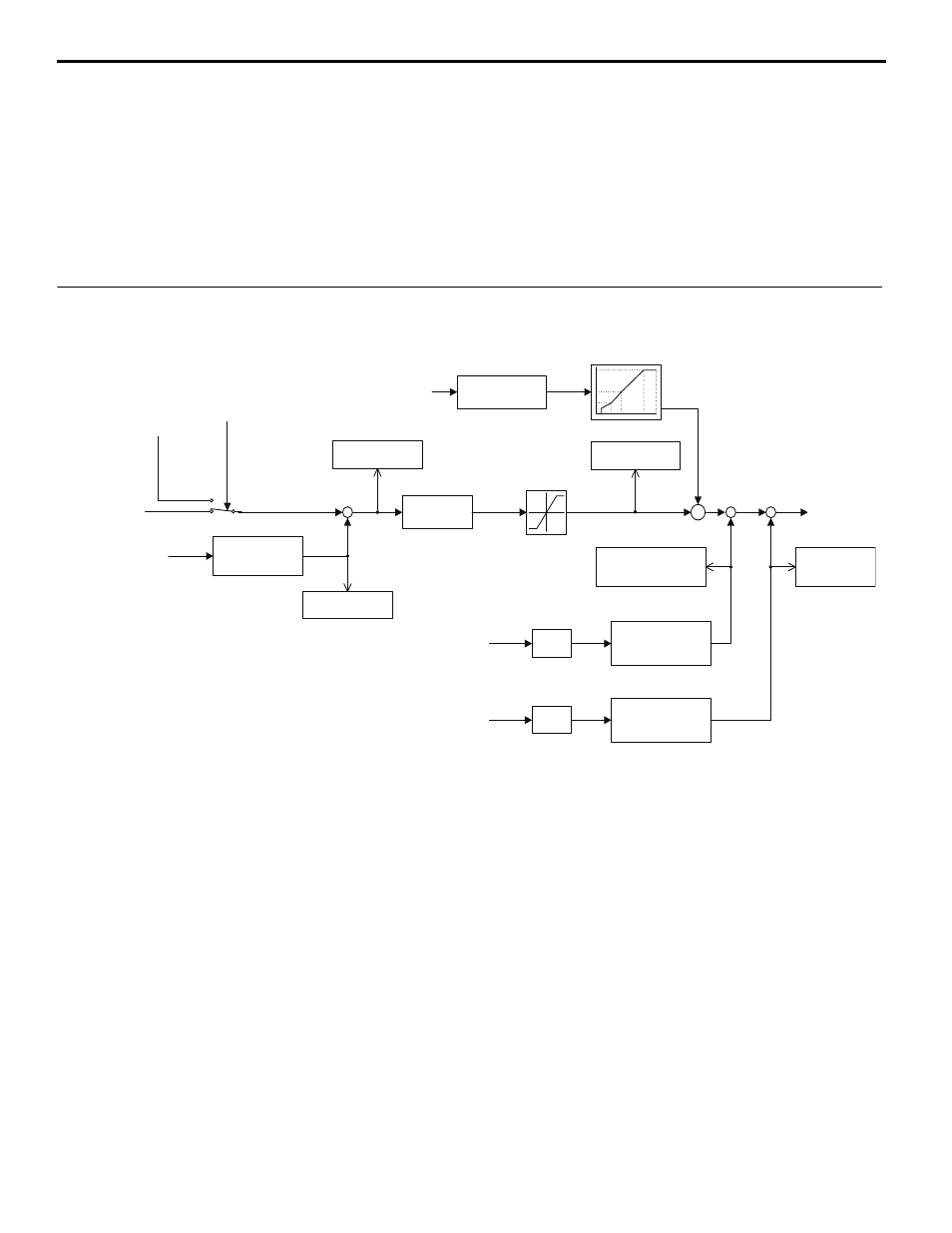
Block Diagram
Figure 2
Figure 2 Output Voltage PID Block Diagram
P1-01
Output Voltage
Setpoint
Terminal A2/A3
H3-0X = 20
Output Voltage Feedback
P1-07
Analog Full Scale
Voltage
+
-
PID
P1-02: Output Voltage Gain
P1-03: Output Voltage Integral Time
P1-04: Output Voltage Integral Limit
P1-05: Output Voltage Derivative Time
U7-02
Voltage Feedback
U7-03
Voltage Error
Frequency
Reference
Accel/Decel
(C1-XX parameters)
+
+
P1-06
Output Voltage Limit
V/f Calculation
(Based on E1-04 ~ E1-10)
Output Voltage
Reference
RMS output
current
Filter
P2-02
Iac RMS FIlter Time
P2-01
Iac RMS
Compensation Voltage
+
+
+
+
Secondary
current Iq
Filter
P2-04
Iq FIlter Time
P2-03
Iq Compensation
Voltage
U7-05
Iac RMS Compensation
Voltage Output
U7-06
Iq Compensation
Voltage Output
U7-04
Voltage PID Output
Terminal A2/A3
H3-0X = 21
PID Voltage Set Point
H3-0X = 21
TRUE
FALSE