Tvoc setup, Selector pins – Ion Science TVOC User Manual
Page 9
TVOC MANUAL
Ion Science Ltd
Page 9 of 32
Unrivalled Detection. www.ionscience.com
Diagram 3
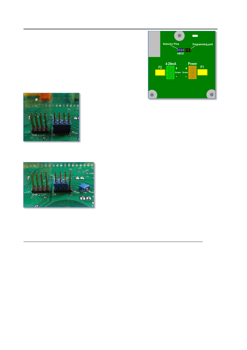
TVOC setup
Selector Pins
TVOC has a number of settings that can be selected by the
user via a row of four selector pins mounted on the reverse side
of the main PCB. Diagram 2 shows the location of the functional
selector pins labelled - A, B, C & D.
The selector pins absence or presence determines the chosen
setting.
TVOC is shipped with all four selector pins fitted as shown in
diagram 3.
Diagram 4 shows the removal of 1 selector pin.
The following table shows the selector pin combinations and the corresponding function.
= Selector pin fitted
= Selector pin removed
Selector pin
A
B
C
D
Range
Displayed units
1000
ppm (Default)
x
100
ppm
x
10
ppm
x
2280
mg/m
3
x
x
228
mg/m
3
x
x
22.8
mg/m
3
Selector pin ‘B’ and ‘C’ selects the ranges
-
10 ppm, 100 ppm or 1000 ppm
Selector pin ‘D’ selects the units
-
ppm’ or ‘mg/m
3
Selector pin ‘A’
-
Fault output range
NOTE: During an Alarm condition (F1 or F2) the output will drop to either 3.5 mA or 2.0 mA.
Jumper ‘A’ fitted: 3.5 mA during an alarm condition
Jumper ‘A’ removed: 2.0 mA during an alarm condition.
As default, the TVOC has a 100 ppm factory calibration
Diagram 2
Diagram 4