KACO Powador-protect User Manual
Page 28
Page 28
A
8.3 Digital output "inverter off"
Country settings: "Germany", "IT-CEI021", "User Defined"
Output signal: Status "On": 12 V clocked, status "Off": 0 V.
NOTE
The digital output can only be used with suitable KACO
inverters. When using devices from other manufacturers
or in combination with KACO inverters, external tie
circuit-breakers must be used.
CAUTION
Equipment damage on short circuit
Destruction of the device if the digital output is short
circuited.
›
Do not short circuit the digital output.
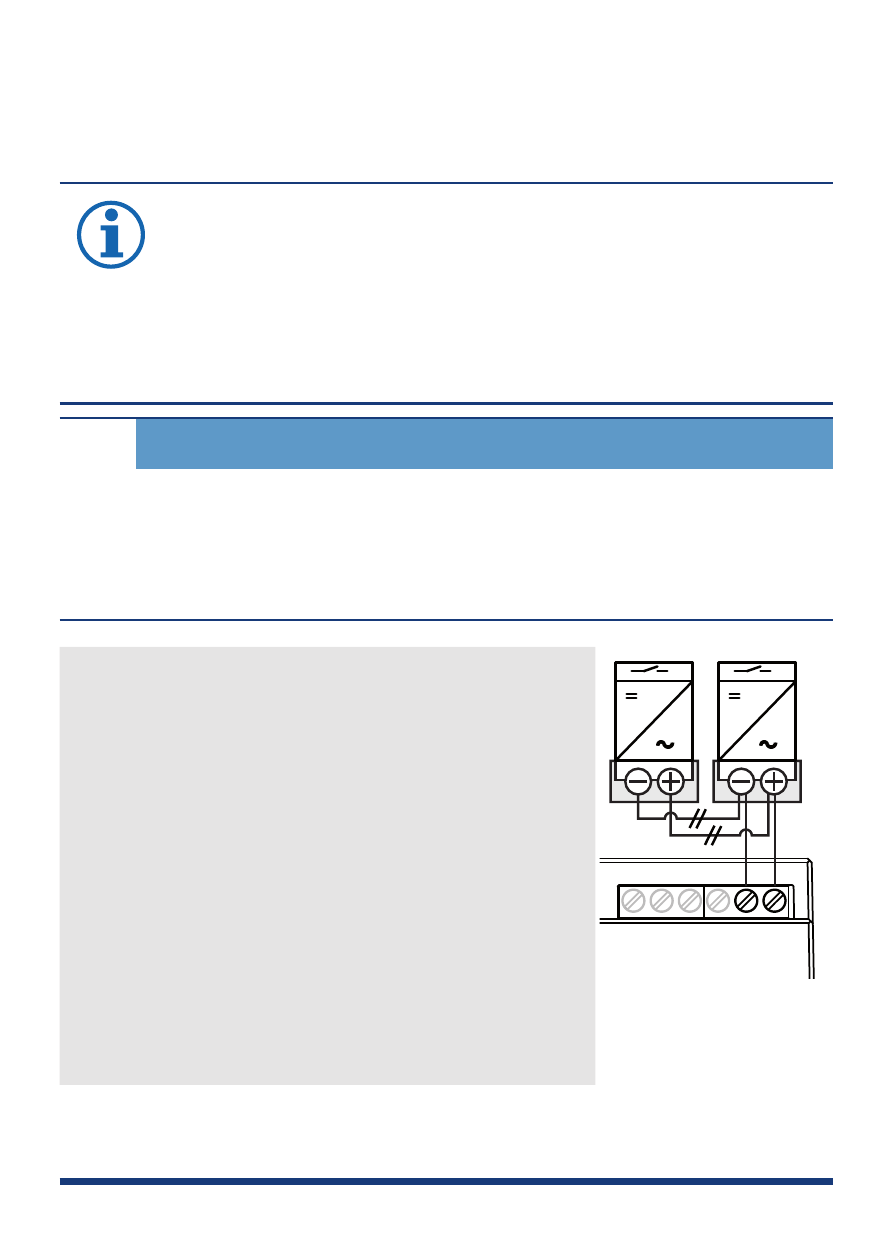
1. Connect wire A (+) to the terminal
marked "EVU+" on the first inverter via
the "DO1" terminal on the first inverter
(see Figure 11).
2. Connect wire B (-) to the terminal
marked "EVU-" on the first inverter via
the "GND" terminal of the first inverter
(see Figure 11).
3. Connect the other inverters to one
another as follows:
D01
GND
4
3
2
1
–
Wire A (+) to wire A (+) and
–
wire B (-) to wire B (-).
Figure 11: Digital
output