The development kit demonstration software – Linx Technologies MDEV-xxx-DT User Manual
Page 8
– –
– –
10
11
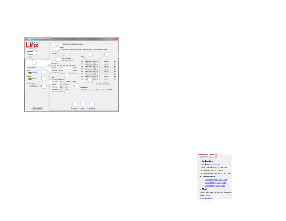
The Development Kit Demonstration Software
The development kit includes software that is used to configure and control
the module through the Programming Dock. The software defaults to
the Advanced Configuration tab when opened (Figure 10). This window
configures the module’s settings.
1. Clicking the Contact Linx, Documentation and About labels on the
left side expands them to show additional information and links to the
latest documentation. This is shown in Figure 11.
2. The Help window shows tips and comments about the software.
3. The active module is connected to the PC and being configured by the
software.
4. Available modules are connected to the PC but are not currently being
configured or controlled by the software.
5. Known Modules are not currently connected to the PC, but have either
been connected to the software in the past or have been manually
entered.
6. The memory setting configures the software to read and write from
either volatile memory or non-volatile memory.
7. The Device Type section configures the module as either an Access
Point, End Device or Range Extender.
8. The Encryption Key box shows the module’s 16 byte AES encryption
7
4
1
2
3
10
6
8
5
9
Figure 10: The Master Development System Software Advanced Configuration Tab
key. This can only be read from modules configured as an AP.
9. The Address box shows the module’s current local address. The
Network ID is the identifier of the network that the module is in. No
other module with the same Network ID can have the same Address.
10. The Joined Modules list shows all of the modules that have joined
with the current module. An ED and RE are only joined with an AP, so
they have one entry. An AP can be joined to up to 50 other modules,
including up to 4 REs.
11. The Radio section configures the radio functions. The checkboxes
select which RF channels are used. The TX Power menu sets the
transmitter output power. The data rate menu sets the serial UART
data rate, which the module uses to configure the over-the-air data
rate. The RSSI Readback shows the RSSI value of the last good
packet that was received.
12. The GPIO Expander Type menus configure the eight GPIOs as digital
inputs, digital outputs or analog inputs. The digital inputs are also
configured to use internal pull-up or pull-down resistors, or set to
high-impedance. High impedance deactivates the internal resistors.
13. The Status column shows the current status of all of the GPIO lines on
the active module.
14. The Internal 20kohm radio button sets the internal resistors as either
pull-up or pull-down.
15. The module identity box shows the active module’s name, firmware
version and serial number.
16. The Read All button reads all of the values.
17. The Submit button writes all changes to the active module.
18. The Set Defaults button restores all settings to the factory defaults.
Figure 11: The Master Development System Software Additional Information
12
13
14
15
16
17
18
11