Linx Technologies MDEV-xxx-RC User Manual
Page 13
–
–
–
–
20
21
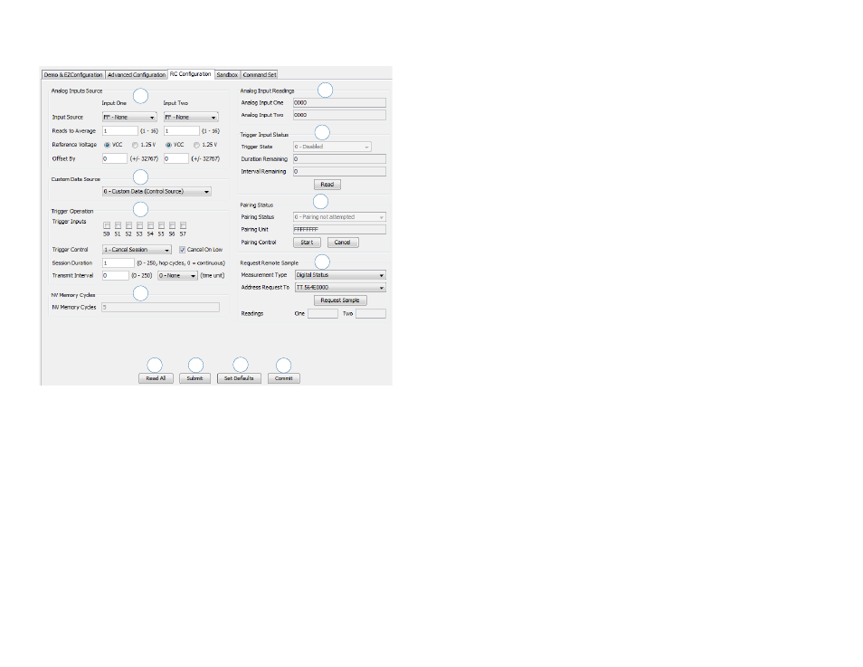
The RC Configuration tab (Figure 21) allows configuration of the module’s
advanced remote control features.
1. The Analog Inputs Source area configures which lines are analog
inputs, the number of readings to average, the reference voltage and
the offset for each channel.
2. The Custom Data Source menu sets the source of custom data
transmitted with each IU message.
3. The Trigger Operation area configures which lines are triggered inputs,
their type of control, session duration and transmit interval.
4. The NV Memory Cycles show how many times data has been written
to the module’s non-volatile memory. The module is capable of
approximately 1,000 writes to NV memory before it wears out. This
count gives an indication of how many more times the module can be
written.
5. The Analog Input Readings show the current analog measurements.
6. The Trigger Input Status shows the current states of the trigger lines.
Figure 21: The Master Development System Software RC Configuration Tab
7
4
1
2
3
10
6
8
11
5
9
12
7. The Pairing Status area shows the current status of any pairing
operations.
8. The request Remote Sample configures the module to request a
response from a remote unit. This area configures the type of sample
that should be in the response and the address of the unit that should
respond.
9. The Read All button reads all of the current configurations from the
active module.
10. The Submit button writes all changes to the active module.
11. The Set Defaults button restores the active module to factory default
conditions.
12. The Commit button writes any changed configurations to non-volatile
memory. The changes should be written to the module using the
Submit button first, then the Commit button is used to make the
changes permanent.