Using the prototype board – Linx Technologies MDEV-xxx-RC User Manual
Page 8
–
–
–
–
10
11
Supply for the module is connected through R17. This can be removed and
replaced by another supply or used to measure the current consumption of
the module.
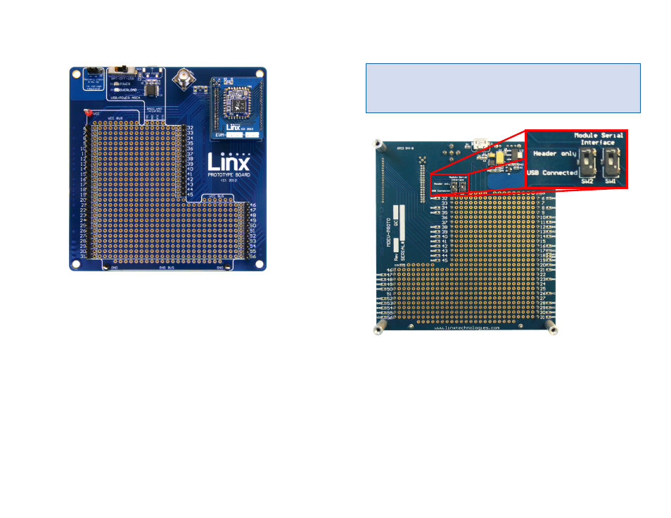
Figure 11 shows the bottom of the board.
SW1 and SW2 connect the USB interface to the Command Data Interface
lines on the module. This allows the prototype board to be used with the
development kit software or a custom application. When in the “USB
Connected position”, the module is connected to the USB interface. The
“Header Only” position connects the module to the header.
Footprints for 0603 size resistors are on most lines so that pull-ups or
pull-downs can easily be added to the lines. The pads are connected to
V
CC
or GND based on the most common configuration for the module. The
schematic at the end of this document shows how each line is connected.
Using the Prototype Board
Snap a Carrier Board onto the socket on the Prototype Board as shown in
Figure 10.
Connect a micro USB cable into the connector at the top of the board.
Plug the other end into a PC or any USB charger. The board is powered
by the USB bus. This board features a prototyping area to facilitate the
addition of application-specific circuitry. The prototyping area contains a
large area of plated through-holes so that external circuitry can be placed
on the board. The holes are set at 0.100” on center with a 0.040” diameter,
accommodating most industry-standard SIP and DIP packages.
At the top of the prototyping area is a row connected to the 3.3V power
supply and at the bottom is a row connected to ground. External circuitry
can be interfaced to the transceiver through the breakout headers. The
numbers next to the headers correspond to the pin numbers on the Carrier
Board. Figure 5 shows the pin assignments for the Carrier Board.
The OVERLOAD LED indicates that that too much current is being pulled
from the USB bus. This is used to prevent damage to the parts or the bus.
The overload condition is reset once the excess current draw is removed.
Figure 10: Prototype Board with a Carrier Board
Note:
The onboard 3.3-volt regulator has approximately 400mA
available for additional circuitry when plugged into a PC. If more current
is required, the user must power the board from an external supply or a
USB charger with more current capabilities, up to 1A.
Figure 11: Prototype Board Bottom Side