Initial setup, Using the programming dock – Linx Technologies MDEV-xxx-RC User Manual
Page 6
–
–
–
–
6
7
Initial Setup
There are several boards that are included with the Development System.
The Carrier Boards have a HumRC
TM
Series transceiver on a daughter
board with headers. These boards snap into sockets on the other boards,
enabling the modules to be easily moved among the test boards.
There are two Programming Docks that have a socket for a Carrier
Board and a USB interface for connection to a PC. This is used with the
demonstration software included with the kit to configure the module
through its Command Data Interface.
There are two Remote Control Demo Boards that are populated differently.
Board A has the buttons on the right column and board B has them on the
left column. These accept the Carrier Boards and are used to demonstrate
the remote control functionality of the HumRC
TM
Series. They can also be
used for range testing. These boards use hardware configuration, so if any
changes have been made to the modules using the software then they
may not operate correctly. A restore to default configuration can be used to
reset the modules.
There are two Prototype Boards that have a socket for a Carrier Board, a
USB interface and a large area of plated through holes that can be used to
develop custom circuitry. The board can be powered either from the USB
connection or an external battery.
The development software supports Windows XP, Vista, 7, 8, and 8.1;
OS X 10.6 ‘Snow Leopard’ or later (including Lion, Mountain Lion, and
Mavericks); any version of Linux with Java 1.6 or later.
Warning:
Installing or removing a Carrier Board while power is
applied could cause permanent damage to the module. Either turn
off power to the board or unplug the USB cable before installing or
removing a Carrier Board
!
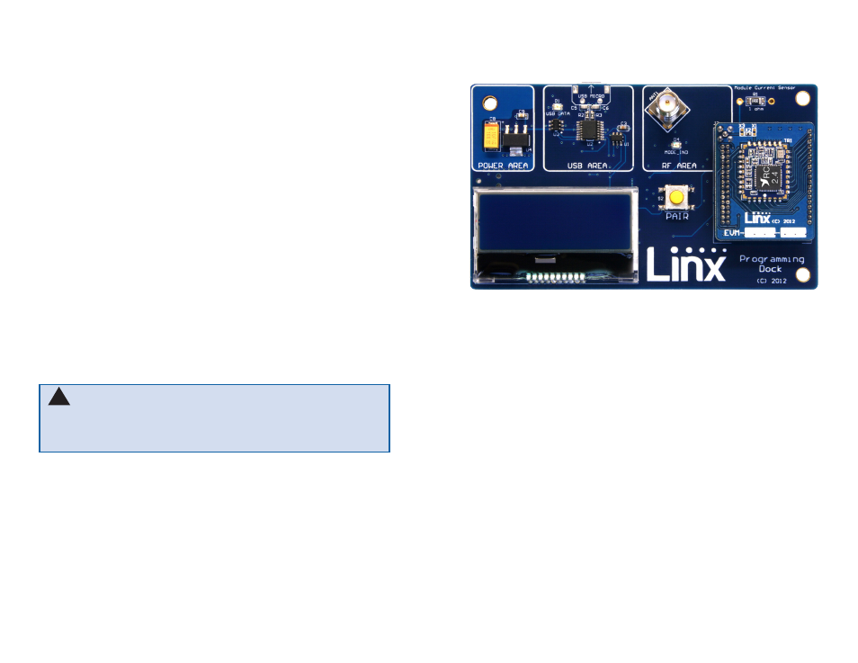
Using the Programming Dock
Snap a Carrier Board onto the socket on the Programming Dock as shown
in Figure 8.
Connect a micro USB cable into the connector at the top of the board.
Plug the other end into a PC. The board is powered by the USB bus.
The demonstration software included with the kit or custom application
software can be used to configure the module through its Command
Data Interface. The LCD is used to display information about the module.
This includes the module’s local address and a custom nickname. The
nickname is entered using the development kit software and can be
any name that helps distinguish the modules from one another. This is
convenient when multiple programming docks are connected to the same
computer. Please see the development kit software section for more
information on the nicknames.
The HumRC
TM
Series transceiver has a serial Command Data Interface
that offers the option to configure and control the transceiver through
software instead of through hardware. This interface consists of a standard
UART with a serial command set. This allows for fewer connections in
applications controlled by a microcontroller as well as for more control and
advanced features than can be offered through hardware pins alone.
Figure 8: Programming Dock with a Carrier Board