Linx Technologies MDEV-xxx-RC User Manual
Page 16
Advertising
–
–
–
–
26
27
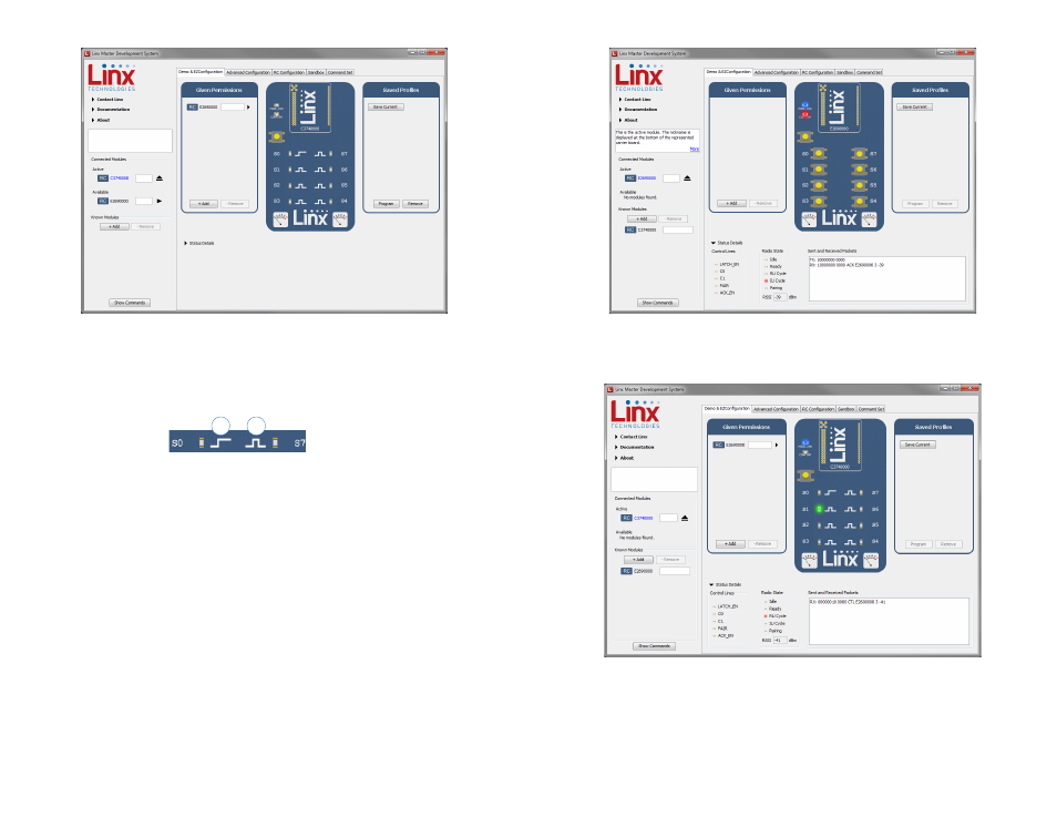
The buttons have all changed to LEDs. The symbol next to each LED
indicates if it is latching or momentary (Figure 30). S0 is latching, the rest
are momentary.
Now that the modules are configured their use can be demonstrated.
Clicking a button on the transmitter module activates an LED on the
receiving module. Figure 31 shows the transmitter, Figure 32 shows the
receiver.
Figure 29: The Master Development System Software Demo and EZConfiguration Tab with Changes
Figure 30: The Master Development System Software Latching (1) and Momentary (2) Symbols
1
2
Figure 31: The Master Development System Software Transmitting Module
Figure 32: The Master Development System Software Receiving Module
Advertising