Ordering information, Absolute maximum ratings, Electrical specifications – Linx Technologies TXM-xxx-LR User Manual
Page 4
– –
– –
2
3
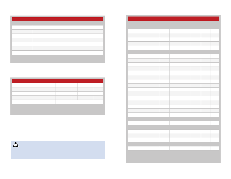
LR Series Transmitter Specifications
Parameter
Symbol
Min.
Typ.
Max.
Units
Notes
Power Supply
Operating Voltage
V
CC
2.1
3.0
3.6
VDC
Supply Current
l
CC
3.4
mA
1,2
Logic High
5.1
mA
2
Logic Low
1.8
mA
Power Down Current
l
PDN
5.0
nA
Transmitter Section
Transmit Frequency Range
F
C
TXM-315-LR
315
MHz
TXM-418-LR
418
MHz
TXM-433-LR
433.92
MHz
Center Frequency Accuracy
–50
+50
kHz
Output Power
P
O
–4
0.0
+4
dBm
2
Output Power Control Range
–80
+10
dB
3
Harmonic Emissions
P
H
–36
dBc
Data Rate
DC
10,000
bps
Data Input:
Logic Low
V
IL
0.25
VDC
Logic High
V
IH
V
CC
–0.25
VDC
Power Down Input:
Logic Low
V
IL
0.25
VDC
Logic High
V
IH
V
CC
–0.25
VDC
Antenna Port
RF Output Impedance
R
OUT
50
Ω
4
Timing
Transmitter Turn-On Time
Via V
CC
or PDN
1.0
ms
4
Modulation Delay
30.0
ns
4
Environmental
Operating Temperature
–40
+85
ºC
4
Electrical Specifications
1. With a 50% duty cycle
2. With a 750
Ω resistor on LADJ
3. See Figure 6 on page 4
4. Characterized, but not tested
Ordering Information
Ordering Information
Part Number
Description
TXM-315-LR
315MHz Transmitter
TXM-418-LR
418MHz Transmitter
TXM-433-LR
433MHz Transmitter
RXM-315-LR
315MHz Receiver
RXM-418-LR
418MHz Receiver
RXM-433-LR
433MHz Receiver
EVAL-***-LR
LR Series Basic Evaluation Kit
*** =
315, 418 (Standard), 433MHz
Transmitters are supplied in tubes of 50 pcs.
Figure 2: Ordering Information
Absolute Maximum Ratings
Absolute Maximum Ratings
Supply Voltage V
cc
−0.3
to
+3.6
VDC
Any Input or Output Pin
−0.3
to
V
CC
+ 0.3
VDC
Operating Temperature
−40
to
+85
ºC
Storage Temperature
−40
to
+90
ºC
Soldering Temperature
+260ºC for 10 seconds
Exceeding any of the limits of this section may lead to permanent damage to the device.
Furthermore, extended operation at these maximum ratings may reduce the life of this
device.
Figure 3: Absolute Maximum Ratings
Warning:
This product incorporates numerous static-sensitive
components. Always wear an ESD wrist strap and observe proper ESD
handling procedures when working with this device. Failure to observe
this precaution may result in module damage or failure.
Figure 4: Electrical Specifications