Using the ladj line, Power supply requirements, Transferring data – Linx Technologies TXM-xxx-LR User Manual
Page 8
– –
– –
10
11
Using the LADJ Line
The Level Adjust (LADJ) line allows the transmitter’s output power to be
easily adjusted for range control, lower power consumption, or to meet
legal requirements. This is done by placing a resistor between V
CC
and
LADJ. The value of the resistor determines the output power level. When
LADJ is connected to V
CC
, the output power and current consumption
are at the maximum. Figure 6 on page 4 shows a graph of the output
power vs. LADJ resistance.
This line is very useful during FCC testing to compensate for antenna
gain or other product-specific issues that may cause the output power
to exceed legal limits. A variable resistor can be temporarily used so that
the test lab can precisely adjust the output power to the maximum level
allowed by law. The variable resistor’s value can be noted and a fixed
resistor substituted for final testing. Even in designs where attenuation is
not anticipated, it is a good idea to place a resistor pad connected to LADJ
and V
CC
so that it can be used if needed. For more sophisticated designs,
LADJ can be also controlled by a digital potentiometer to allow precise and
digitally variable output power control.
Power Supply Requirements
The module does not have an internal
voltage regulator; therefore it requires a
clean, well-regulated power source. While
it is preferable to power the unit from a
battery, it can also be operated from a
power supply as long as noise is less than
20mV. Power supply noise can affect the
transmitter modulation; therefore, providing
a clean power supply for the module should
be a high priority during design.
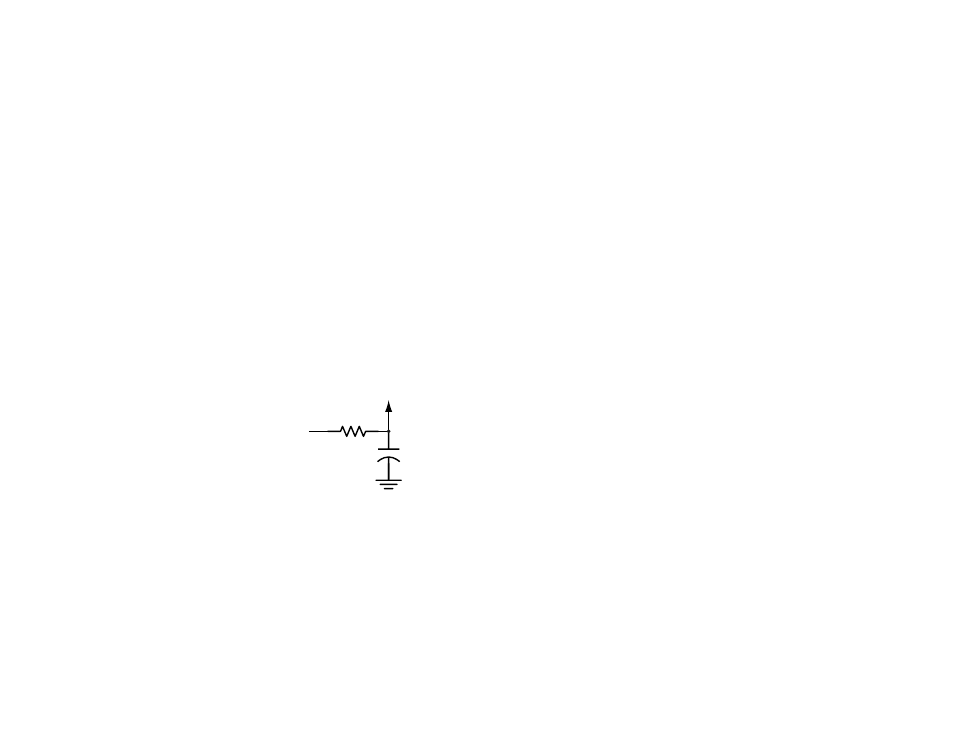
A 10
Ω resistor in series with the supply followed by a 10μF tantalum
capacitor from V
CC
to ground will help in cases where the quality of the
supply is poor. Note that the values may need to be adjusted depending on
the noise present on the supply line.
Transferring Data
Once a reliable RF link has been established, the challenge becomes how
to effectively transfer data across it. While a properly designed RF link
provides reliable data transfer under most conditions, there are still distinct
differences from a wired link that must be addressed. Since the LR Series
modules do not incorporate internal encoding or decoding, a user has
tremendous flexibility in how data is handled.
If the product transfers simple control or status signals such as button
presses or switch closures and it does not have a microprocessor on board
(or it is desired to avoid protocol development), consider using a remote
control encoder and decoder or a transcoder IC. These chips are available
from a wide range of manufacturers including Linx. They take care of all
encoding and decoding functions, and generally provide a number of data
pins to which switches can be directly connected. In addition, address bits
are usually provided for security and to allow the addressing of multiple
units independently. These ICs are an excellent way to bring basic remote
control / status products to market quickly and inexpensively. Additionally,
it is a simple task to interface with inexpensive microprocessors, IR, remote
control or modem ICs.
It is always important to separate the types of transmissions that are
technically possible from those that are legally allowable in the country
of intended operation. Linx Application Notes AN-00125, AN-00128
and AN-00140 should be reviewed, along with Part 15, Section 231 of
the Code of Federal Regulations for further details regarding acceptable
transmission content in the US All of these documents can be downloaded
from the Linx website at www.linxtechnologies.com.
Another area of consideration is that the data structure can affect the
output power level. The FCC allows output power in the 260 to 470MHz
band to be averaged over a 100ms time frame. Because OOK modulation
activates the carrier for a ‘1’ and deactivates the carrier for a ‘0’, a data
stream that sends more ‘0’s has a lower average output power over
100ms. This allows the instantaneous output power to be increased, thus
extending range.
Figure 11: Supply Filter
+
10
Ω
10
µF
Vcc IN
Vcc TO
MODULE