Kichler 300001 User Manual
Page 10
9
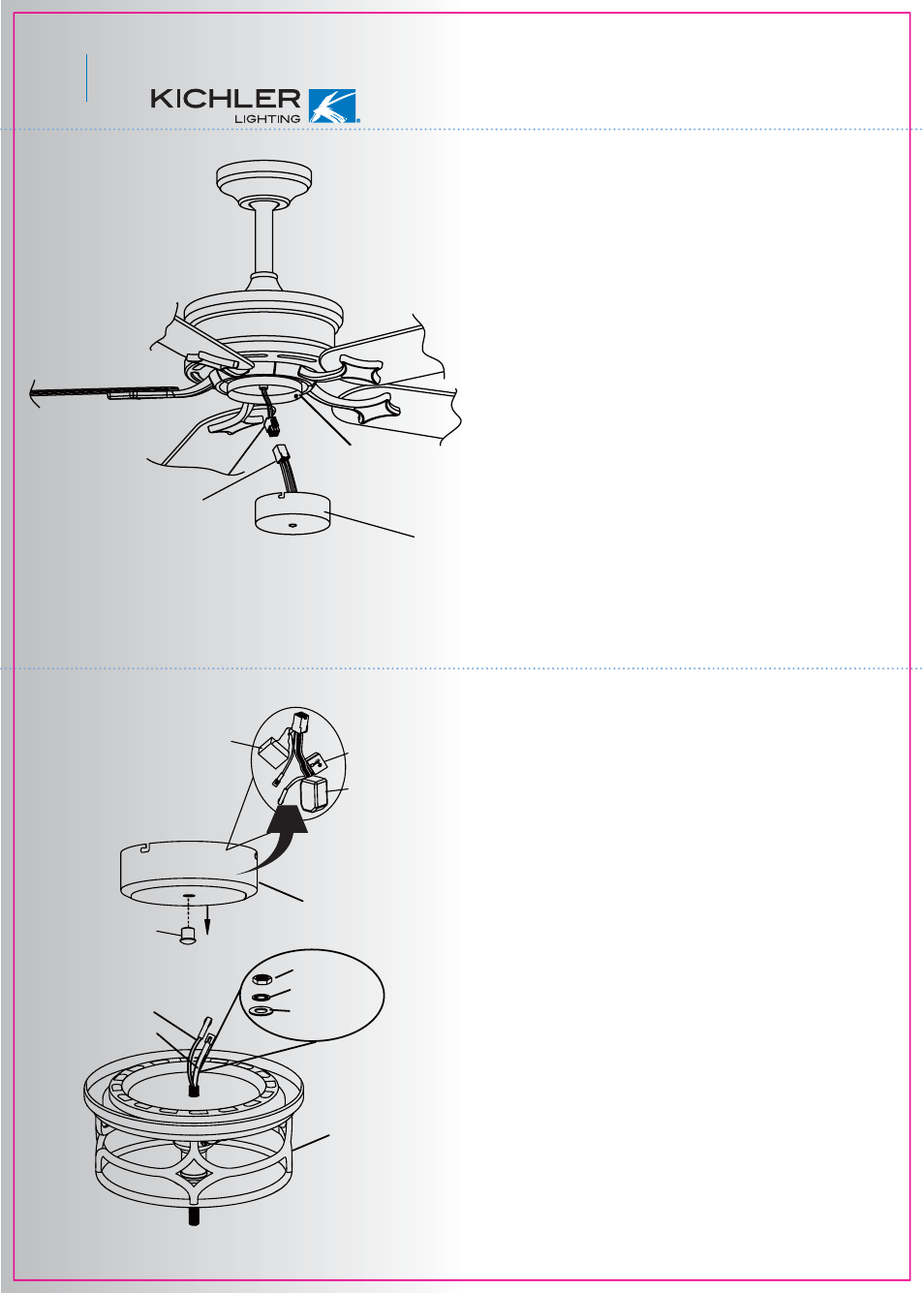
Fig. 20
Fig. 19
12. INSTALLING THE LIGHT KIT
11. INSTALLING THE SWITCH HOUSING
Connection plug
Mounting plate
Switch housing
NOTE: Before continuing, make sure the power
is disconnected by turning off the circuit breaker
of removing the fuse at the circuit box.
Step 1. Loosen the 3 screws on the switch
house mounting plate.
Step 2. The square plastic wiring connectors
from the ceiling fan and the switch housing will
only fit together one way. Match up the color on
the side of the connectors, then push them
together until the snap engages.
Step 3. Tuck the connections neatly into the
switch housing. Align the key holes on the
switch housing with the screws on the mounting
plate. Turn the switch housing until it locks in
place at the narrow end of the key holes.
Tighten all 3 screws previously loosened.
(Fig. 19)
Step 1. Remove th finial NUT located in the
center of the switch housing. See Fig. 20.
Step 2. Remove the hex nut, lock washer and
metal washer from the light fixture mounting
stem.
Step 3. Feed the electrical wires from the light
fixture through the hole in the switch housing
(starting with th black wire first, it has a larger
connector). Threaded th light kit onto the
switch housing, add the metal washer, lock
washer and hex nut on the inside of the switch
housing and tighten securely. (Fig. 20)
NOTE: Please take the reverse module,
capacitor and 190w power limiter out of the
switch housing prior to threading the light kit to
switch housing.
Mo
de
l N
o:
PL
-1
90
B
AC
12
0V
60
HZ
Po
we
r L
imi
t
Ma
x.1
90
W
(O
N/
OF
F)
Inc
an
de
sc
en
t o
r B
all
as
t
LIG
HT
/B
LA
CK
Capacitor
Limiter
Reverse module
Finial nut
White wire
Black wire
Light kit
Lock washer
Metal washer
Hexnut
Switch housing