Chicago – Kichler 300001 User Manual
Page 7
6
Chicago
TM
Fig. 12
Fig. 13
Code switch
Receiver
Hanger
bracket
Battery Compartment
6. INSTALLATION OF SAFETY SUPPORT
( For Canadian Installation ONLY )
7. MAKE THE ELECTRIC CONNECTIONS
A safety support cable is provided to help prevent
the ceiling fan from failing, please install it as
follows.
Step 1. Attach the provided wood screw and
washers to the ceiling joist next to the mounting
bracket but do not tighten. (Fig. 11-1)
Step 2. Adjust the length of the safety cable to
reach the screw and washers by pulling the extra
cable through the cable clamp until the overall
length is correct, put the end of the cable back
through the cable clamp, forming a loop at the
end of the cable. Tighten the cable clamp
securely. Now, put the loop in the end of the
safety cable over the wood screw and under the
washer. Tighten the wood screw securely. See
Fig. 11-2
WARNING: To avoid possible electrical shock,
be sure the electricity is turned off at the main
circuit breaker or fuse box before wiring.
WARNING: If your house wires are different
colors than referenced in this manual, stop
immediately. A professional electrician is recom-
mended to determine proper wiring.
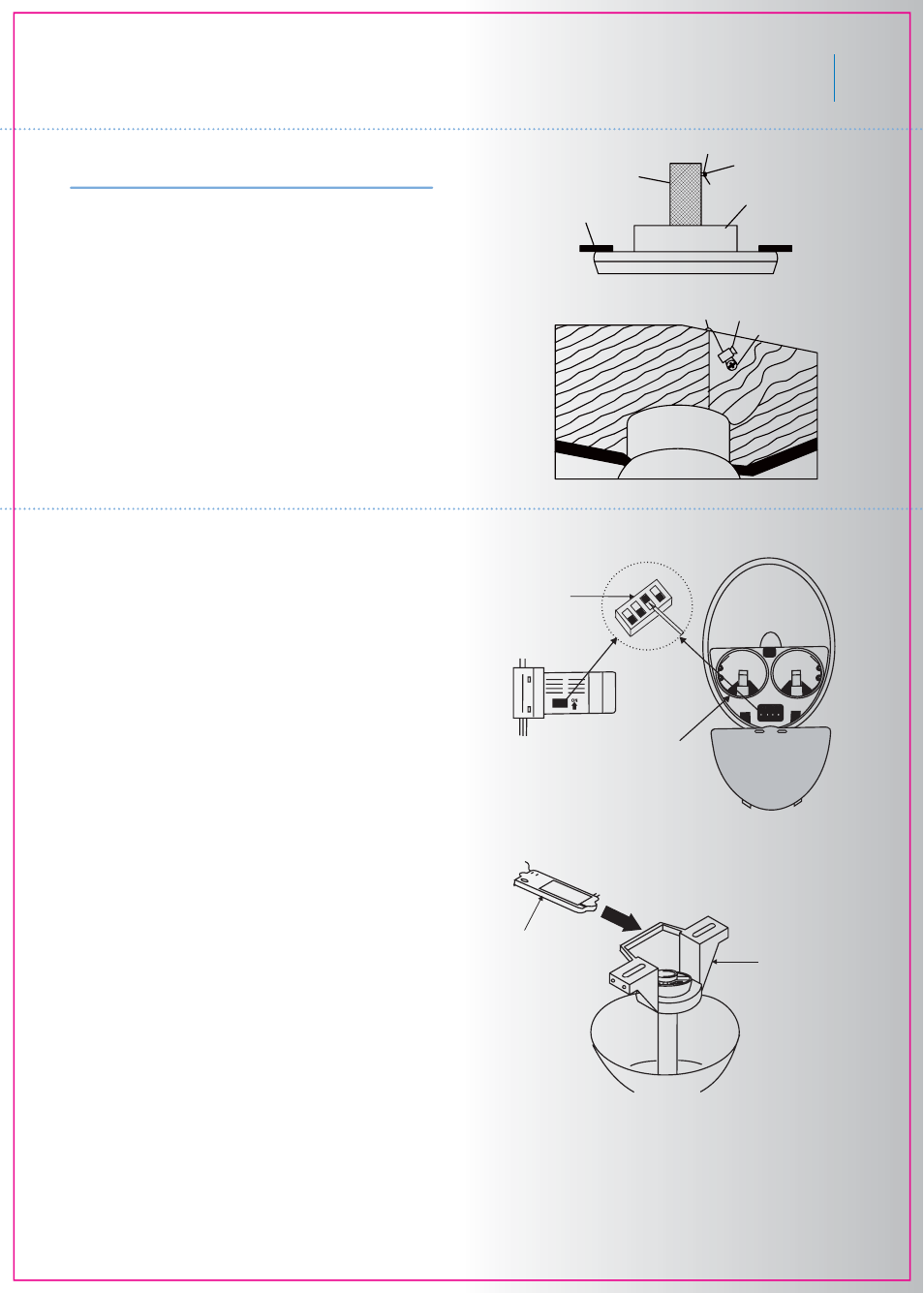
NOTE: The CoolTouch™ Control System is
equipped with 16 code combinations to prevent
possible interference from or to other remote
units. The frequency switches on your receiver
and transmitter have been preset at the factory.
Please recheck to make sure the switches on
the transmitter and receiver are set to the same
position, any combination of settings will position
the fan as long as each switch on the transmitter
and receiver are set to the same position. (Fig.
12) Changing the order of switches on each
switch block, changes the operational frequency.
Step 1. Insert the receiver into the mounting
bracket, with the flat toward the ceiling. (Fig. 13)
Step 2. Motor to Receiver Electrical Connec-
tions:
NOTE: Make all of the following connections
with “Wire Nut” connectors.
Connect the black wire from the fan to black wire
marded “TO MOTOR L” from the receiver. Con-
nect the white wire from the fan to the white wire
marked “TO MOTOR N” from the receiver.
Connect the blue wire from the fan to the blue
wire marked “For Bottom Light” from the
receiver. Place a plastic wire nut on the end of
the Orange Wire coming from the receiver
marked “For Upper Light”. Your ceiling fan is not
equipped with a Upper Light. Secure all the wire
connections with the plastic wire nut provided.
(Fig. 14 on the next page)
Fig. 11-2
Fig. 11-1
Ceiling
Support Brace
Outlet Box
Wood Screw
Flat Washer
Spring Washer
Wood Screw
Safety Cable Cable Clamp