Installation, Manual operation, Port configuration – Marwin Valve 3T3700 Series 3-Way Ball Valve User Manual
Page 2
proper solvent.
After cleaning, ball valves must be lubricated with
an adequate lubricant.
Ball valves should be operated for at least two com-
plete cycles before installing or returning to stor-
age.
Installation
The ball valves may be installed in any position using
standard pipe fitting practice.
CAUTION: Before installation of the valve:
Pipe must be free of tension both during and af-
1.
ter installation.
Pipe must be flushed to clean dirt, welding resi-
2.
dues, etc. which would damage ball or seats.
The valve should be kept in OPEN POSITION dur-
3.
ing installation and protective plastic covers must
be removed only at the moment of installation.
Before shipment, the ball is lubricated with a pure
4.
Vaseline oil. This can be easily removed with an
application compatible solvent if required.
If the valve was specified to be tested per ANSI
5.
16.34, there may be some trapped water be-
tween the ball and the body cavity. This can be
removed by partially opening the valve, thereby
exposing the cavity to the through port of the
ball.
Special care should always be taken when install-
6.
ing automated ball valves that the ball is in the
proper position.
Installation of Threaded Ends
Unless otherwise specified, pipe threads are Amer-
1.
ican National Standard Taper Pipe Threads (NPT)
per ANSI B1.20.1, and require that a pipe sealant
be used.
Use an anti-seize thread sealant to seal and pre-
2.
vent galling.
Marwin recommends PTFE-based liquid sealant
a.
or Grafoil tape as thread sealants.
Notes:
b.
Use all pipe sealant products in accor-
i.
dance with the manufacturer’s instructions
and good piping practices.
Correct lubrication of stainless steel pipe
ii.
threads is especially important to prevent
galling.
To prevent distortion or damage to the valve, do no
3.
apply torque through the valve. When tightening
valve, use wrench on the end nearest the pipe be-
ing tightened.
Always leak test the system before using.
4.
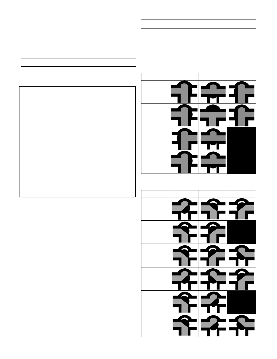
Manual Operation
Refer to the port arrangement diagram for specific valve
operation.
Port Configuration
Three Way “T” Port
A
B
C
T1
180°
T2
180°
T3
90°
T4
90°
Three Way “L” Port
A
B
C
L1
180°
L2
90°
L3
180°
L4
180°
L5
90°
L6
180°
-2-
- 3L3800 Series 3-Way Ball Valve 600 Series - 633FTRS Series - Brass Аква техника 600 Series - 666FTTS - Brass Аква техника 600 Series - DM600-xxx-BR Series - Brass Аква техника 600 Series - 666RTTS - Brass Аква техника DM9000 Series 4600F Series Brass Аква техника, 3 Piece Swing Out 3T3300 Series 3-Way Brass Аква техника 3L3400 Series 3-Way Brass Аква техника 3L/T 2100F-A Series 3-Way Ball Valve 3L/T 2100F -F Series 3-Way Аква техника