RISCO Group WatchOUT PIR Outdoor WL X312 User Manual
Page 11
Installation Manual
11
English
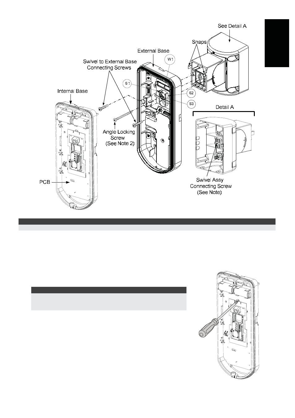
Figure 9
NOTE:
Do not open or close the Swivel Assy Screw since it is used for connecting the swivel parts only (factory tightened).
4. Secure external base to swivel with two screws fastened trough knockouts S1 and S2
(Figure 9).
5. Insert the supplied angle locking screw from the external base through the angle locking screw
knockout S3 on the external base to the standard swivel (Figure 9).
6.
Rotate the Standard Swivel to the desired position. Once the
Standard Swivel is in the desired position, secure the angle
locking screw.
IMPORTANT!
Take care not to tilt the detector upwards and downwards. The
detector should remain perpendicular to the ground for maximum
detection and reliability.
7. Line up the internal base onto the external base. Insert tamper
wiring through the internal base.
8. Secure internal base to external base (Lock I1, Figure 2).
9. To readjust the Standard Swivel when the PCB is installed
(Figure 10):
a. Bend down the black foam located below the RED LED on
the PCB (enough to reach the Swivel locking screw).
b. Use a Hex screwdriver to release the locking screw (see
Figure 10).
c. Rotate the Swivel to the desired position.
d. Secure the angle locking screw.
Figure 10: PCB