Walk test, Important, Led display – RISCO Group WatchOUT PIR Outdoor WL X312 User Manual
Page 9: Operational modes, Transmitter/receiver communication link setup
Installation Manual
9
English
Walk test
Two minutes after applying power, walk test the protected area to verify proper operation.
Adjust the moving PIR for required detection range and reliability.
IMPORTANT!
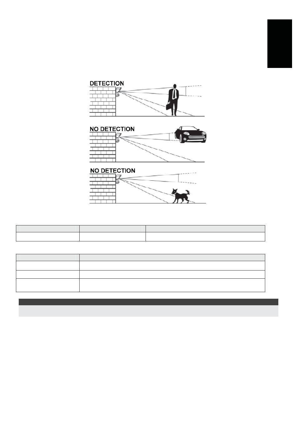
Both upper and lower detection areas must be blocked simultaneously for detection to occur, see
figure 7 below.
Figure 7
LED Display
LED
State
Description
RED
Steady
Indicates ALARM
Operational Modes
Operational Mode
Description
Normal
Dead time (between detection alarms) is 2.5 Minutes.
Test (walk test)
Dead time (between detection alarms) is 2.5 sec.
Write (for enrolling)
The unit transmits a WRITE message each time both the Tamper
Switches (back and cover) are closed for at least 3 seconds.
NOTE:
After power up the detector enters into test mode for a period of 20 minutes (disregarding the DIP Switch Modes
Position).
Transmitter/Receiver Communication link setup
The detector must identify itself to the system’s receiver by writing its coded message into the
receiver’s address memory. This is accomplished by performing the following steps:
1. Set the receiver to Write Mode.
2. Remove the insulation material from the batteries and place them in the batteris holders on
the PCB on the right direction (pay attention to the "+" and "–" diagram on the PCB)
3. Send a WRITE message by closing both of the tamper switches (back and cover) for at least
3 seconds.
4. Verify that the detector has been identified by the receiver.