Introduction, Electrical characteristics, Cpu port pin out – Remote Processing RPC-220 User Manual
Page 24
DIGITAL LINES
SECTION 6
Page 6-1
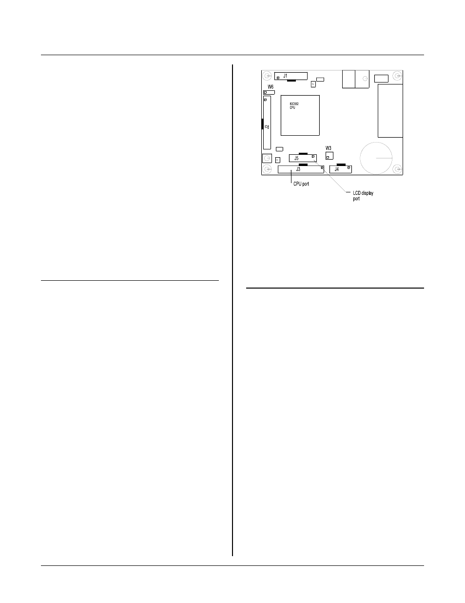
Figure 6-1 CPU Port
DIGITAL LINES
S E C T IO N 6
INTRODUCTION
There are 19 digital lines available. All are from the
CPU , have alternate uses, and are available at J3.
Alternate uses include:
LCD display
PWM output
Interr upts
Counting/timing
S e ri al I/ O
Some lines have 3 uses.
When configuring your system, you will have to make
use of lines based on needed functions and availability.
ELECTRICAL CHARACTERISTICS
Digital ports sink and source a limited amount of
curr ent. Each por t is different a s shown in the table
below:
Ports
Curr ent/condition
P 1. 0 - P 1. 5
1.6 m illi-amp sink
P 1. 0 - P 1. 5
60 micro-amp/source
P 1. 6 - P 1. 7
3.0 m illi-amp/sink
P3, P4
1.6 m illi-amp/sink
P3, P4
60 micro-amp/source
P W M 0, 1
3.2 m illi-amp/sink
P W M 0, 1
400 micro-amp/source
Digital inputs (except P1.6 and P1. 7) have a soft pull up
internal to the CPU. For a m ore robust signal, add a
pull up resistor to the outputs.
Ports P1. 6 and P1.7 ar e open drain output and do not
have inter nal pull up. To use thes e as inputs or output,
make sure the device you are connected to has a pull up
resistor. Otherwise, add one.
Refer to the 80C552 data sheet (file) for more
inform ation on each port.
CPU PORT PIN OUT
Table 6-1 below lists the pin out for CPU port J3. Most
o f th e li ne s at th is p or t co m e fr o m th e C P U .
J3-
Pin
P r i m ar y C P U po r t n a m e
1
P 1. 0
2
P 4. 3
3
P 1. 1
4
From RTC, square wave output
5
P 1. 2
6
INT0 (P3. 2)
7
P 1. 3
8
+ 5V supply
9
P 1. 4
10
System Reset
11
P 1. 5
12
Ground
13
P 4. 5
14
Ground
15
P 1. 6
16
P 4. 4
17
P 1. 7
18
+ 5V supply
19
P 3. 4
20
PWM 1 output
21
P 3. 5
22
PWM 0 output
23
INT 1 (P3. 3)
24
P 4. 6
25
RTC IRQ
26
P 4. 7