Application program – Remote Processing RPC-220 User Manual
Page 41
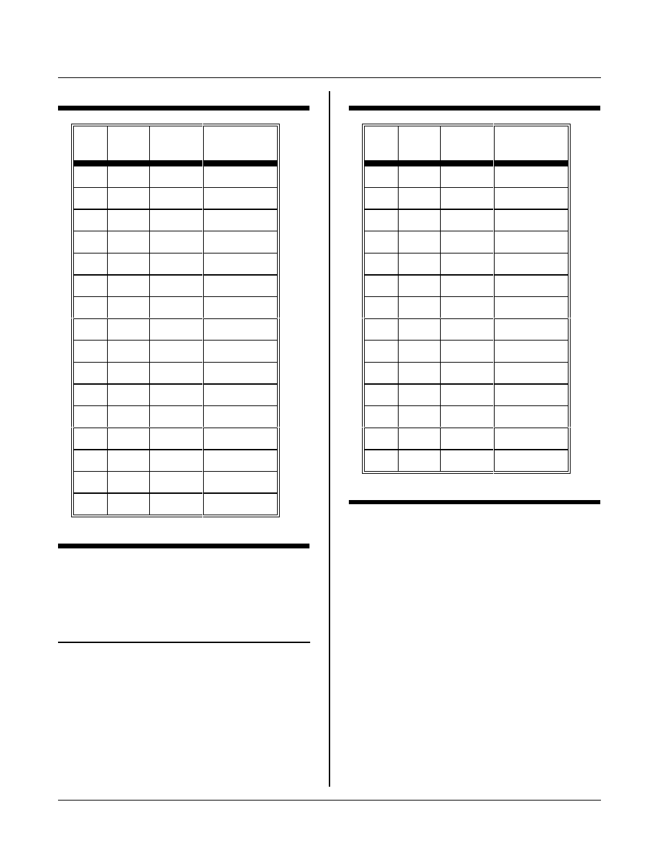
DISPLAY PORT
SECTION 13
Page 13-2
J5
pin
Disp.
pin
Symbol
Function
2
1
DB7
Data bus
1
2
DB6
Data bus
4
3
DB5
Data bus
3
4
DB4
Data bus
6
5
DB3
no connect
5
6
DB2
no connect
8
7
DB1
no connect
7
8
DB0
no connect
10
9
E1
Enable 1
9
10
R / ~W
Read, write
12
11
RS
Reg. select
11
12
Vee
Contr ast V
14
13
Gnd
Ground
13
14
+ 5V
+ 5V
16
15
E2
Enable 2
15
16
N C
No connect
Table 13-2 4 x 40 LCD signal pin out
J5
pin
Disp.
pin
Symbol
Function
14
1
Gnd
Ground
13
2
+ 5V
+ 5 power
11
3
Vee
Contr. adj
12
4
RS
Reg. select
9
5
R / ~W
Read/ write
10
6
E
Enable
8
7
DB0
no connect
7
8
DB1
no connect
6
9
DB2
no connect
5
10
DB3
no connect
3
11
DB4
Data bus 4
4
12
DB5
Data bus 5
1
13
DB6
Data bus 6
2
14
DB7
Data bus 7
Table 13-3 Other LC D pin out
APPLICATION PROGRAM
LCD display program is in the LCD directory.
F i le N a m e
Description
L C D4 40 . C
D e m o / dr i ve r fo r 4 l in e x 4 0 ch a r ac t er L C D
display. Specifically, for P/ N 1723.