Remote Processing RPC-220 User Manual
Page 34
ANALOG INPUT
SECTION 11
Page 12-1
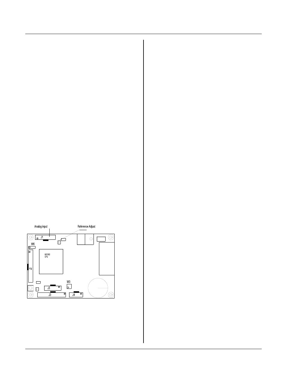
Figur e 11-1 An alog Input and Refer ence Ad j.
INTRODUCTION
A N A L O G IN P U T
SECT ION 11
T h e re a r e e ig h t s in g le e nd e d a n al og to d ig it a l ( A -D )
input channels on the RPC-220. These channels are used
to measure voltages from transducer s, transm itters, 4-20
ma curr ent loops, thermistors, etc. Input voltage range
is 0 to 5 volts with 10 bit (1024) count resolution. Input
impedan ce is 100K ohm s to ground . C onversio n time is
about 28 micro-seconds. Re ference is adjustable to 5.00
±.20 volts.
This section begins with basic information to connect and
use analog inputs. Later, descriptions of how to measure
voltages other than 5 volts and calibration are presented.
CONNECTING ANALOG INPUTS
All analog inputs interface through connector J1. A
STB-20 terminal board and CM A-20 ribbon cable can be
used to provide screw terminal interface. Additional
components, such as resistors and capacitors, may be
connected directly to the scr ew term inals.
For gr eatest accuracy, connect unused inputs to ground.
In environments with high voltage or static electricity,
unused inputs can bleed over to other channels.
R4 may be adjusted to trim accuracy and/ or maximum
voltage to your system. See Calibration later in this
section for more information.
ACQUIRING ANALOG DATA
Analog data is acquired in polled or interrupt fashion.
Polled mode takes about 50 micro-seconds/channel when
written in C. A-D conversion time is about 28 micro-
s e co n ds . R e ad I N PU T S IG N A L C O N SI D E R A TI O N S
below for signal r equireme nts.
INPUT SIGNAL CONSIDERATIONS
Slew Rate
Slew ra te is the rate of signal change . It is usua lly
expressed as volts/second, but other units are also used.
I d ea l ly , s ig n al s p r e se n te d to th e RP C - 2 20 a r e s te a dy , D C
signals. However , this is not a real world situation.
Input signals are always changing.
To get a good reading from the ADC, the input signal
should be relatively stable during the sampling time.
Sampling time begins w hen conve rsion star ts. T o obtain
1/2 LSB (least significant bit) stability, the input signal
should not change more than 2.44 m v in 3.3 micro-
seconds or a rate of 750 volts/second.
The effect of a fast slew rate is a probable conversion
result of 0x3ff. The problem is that a rapidly changing
s ig n al co u pl e s t hr o u gh to th e in p ut of th e in te r n al A D C
comparator, saturating it. This is true when any
channel, selected or not, changes rapidly. The input
signal may change rapidly before any conversion. The
critical time when the signal must be stable is during
conversion.
A way to limit slew rate is to connect an RC filter to the
analog inputs. The time constant should be 500 micro-
seconds or mor e. If a 5 volt P-P sine wave signal is
applied, the maximum frequency is about 600 Hz.
1
Signal Source
The output resistance (impedance) of the signal source
should be as low as possible. If the sourc e impeda nce is
too high, there will be a voltage drop over the source
resistance.
The voltage over the output impedance is primarily due
to the 100K ohm pull dow n resistors at the analog inputs.
For 1/ 2 LSB accuracy, source impedance should be 50
ohms or less.
The resistor network R1 can be removed to allow an
increase in source resistance . If yo u do this, then all
unused inputs must be grounded.