Serial ports chapter 4 – Remote Processing RPC-30 User Manual
Page 14
SERIAL PORTS
CHAPTER 4
Page 12
RPC-30
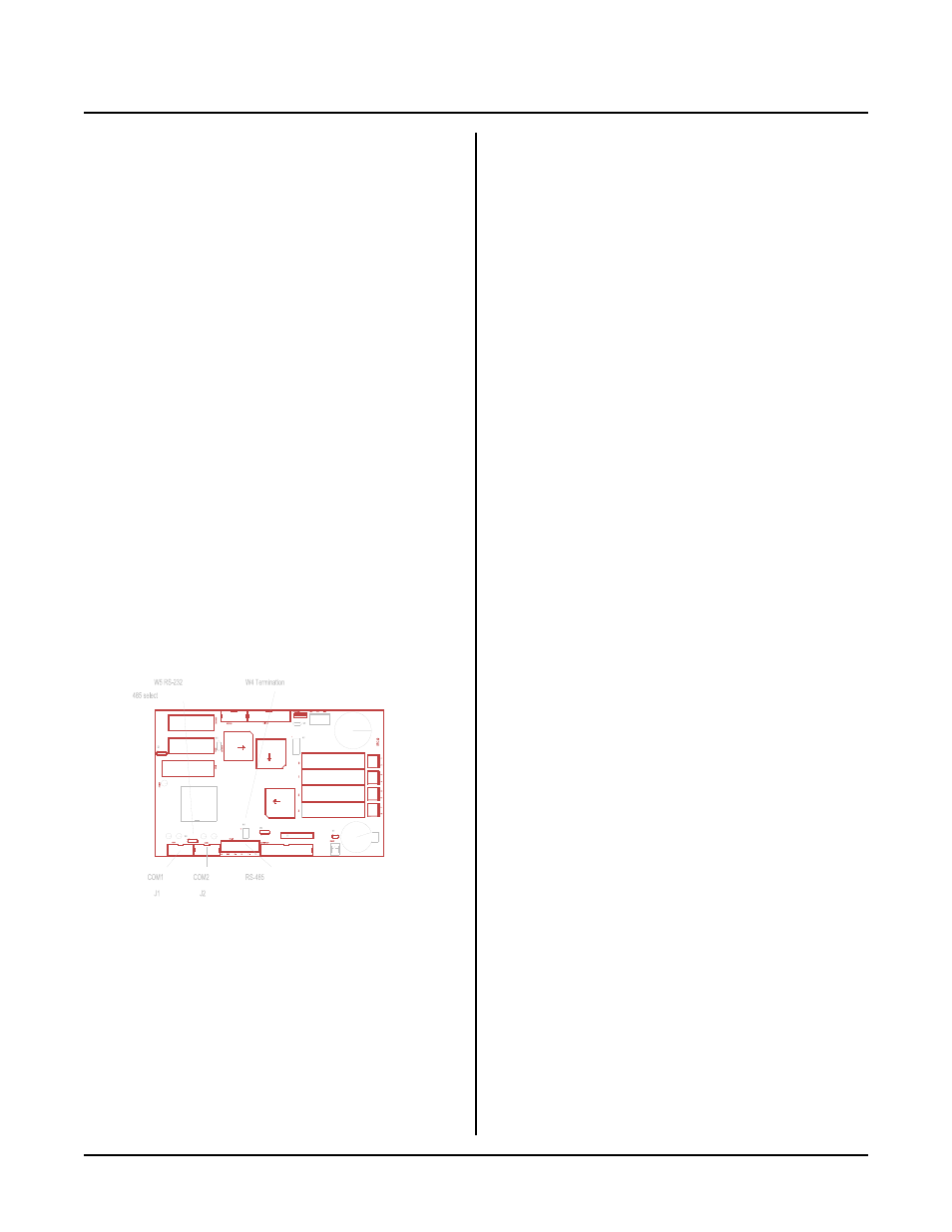
Figure 4-1 Serial ports
DESCRIPTION
The RPC -30 has two serial ports that can be used for
interfacing to a printer, term inal, RS-485 network, or
other ser ial devices. This chapte r descr ibes their
characteristics and how to use them. F requent
references are m ade to commands listed in the
CAMBA SIC Programming Manual . P lease ref er to this
manual for more infor mation about these com mands.
Serial por ts are num bered C OM 1 and CO M2. COM 1 is
used for program development. During run time, it can
be used for other functions. C OM2 is a general purp ose
port and can be used as either RS-232 or RS-422/485.
Both ports sup port XO N/ XOF F pr otocol to contr ol data
transmission. Each por t has a 256 character interrupt
driven inp ut and output bu ffer. This allow s charac ters to
be sent out (using PRINT) without slowing down
program execution. Howeve r, if the PRINT buffer fills,
program execution is suspended until the buffer em pties.
Both ports have a 256 character input buffer. When
more than 256 character s have been rece ived, exc ess
ones are ignored.
The baud rate, parity, data length, and stop bit length are
changed using the CONF IG BAUD command.
COM1 SERIAL PORT
This port uses a VTC-9F serial cable to connect external
serial dev ices to the por t. T he cable con sists of a 10 pin
IDC connector wired one-to-one to a DB-9 connector.
Line 10 is sim ply cut off. The pinou t is designed so it
plugs directly into the 9 pin serial port connector on a
P C .
COM 1 does not use hardware handshake lines. T he
CTS line is pulled high in case external equipment uses
this line.
This port is normally used for program ming. D uring
run tim e it may be u sed as a gene ral pur pose seria l port.
W h e n u s ed f or p r og r a m mi ng o r w i th th e IN P U T
s ta t em e n t, i t wi ll ac c ep t A S C II c ha r a ct e r v a lu e s f r om 0
to 127. When used with the INKEY$ and COM$
functions, it will return ASCII values from 0 to 255.
COM2 SERIAL PORT
COM 2 is either an RS-232 or RS-422/48 5 port. It also
uses a VTC-9F serial cable, described above, for RS-232
level communications. COM2 is identical to COM1
except that COM 2 has 2 hardw are handshaking lines,
CTS and RT S. W hen RT S goes low, the RPC -30 is held
off from transmitting out COM2. The status of this port
is read by the BIT statement. The exam ple below
returns the status of the RTS line:
100 B = BIT(194,5)
If B = 1, transm ission is held off.
The CT S line may be set high or low to hold off
comm unication. Line 400 se ts CTS low and 50 0 sets it
high.
400 BIT 192,4,1
500 BIT 192,4,0
Jumper W 5 determines if COM 2 is RS-232 or RS-
422/485.
[1-2]
RS-485
[2-3]
RS-232 (de fault)
The CO NFIG BAUD statement sets the configuration of
this port.
Termination network
When the RPC -30 is the last physical unit on a network,
or it is the only unit (RS-422), the receiver m ust be
term inated to pr event ring ing. Jumper block W4 installs
or re moves this n etwor k. Se t W4 acc ording to the table
below:
[1-3],[2-4]
Termination network installed
[3-5],[4-6]
Termination network removed