Notice – Thermo Pride Spirit Gas TP9C Modulating ECM 97.5% User Manual
Page 35
1083292-UIM-A-0114
Johnson Controls Unitary Products
35
Specially Engineered Installations
The above requirements shall be permitted to be waived where special
engineering, approved by the authority having jurisdiction, provides an
adequate supply of air for combustion and ventilation.
VENT BLOWER ROTATION
For ease of venting, the vent blower may be rotated 90° in either direc-
tion. For upflow installations the vent may exit through the top or either
side of the cabinet. For downflow installations, the vent blower must be
rotated so that the vent exits through either side of the cabinet. See Fig-
ures 29-32 for illustrations of different inducer rotation positions.
SECTION VIII: START-UP AND
ADJUSTMENTS
The initial start-up of the furnace requires the following additional
procedures:
When the gas supply is initially connected to the furnace, the gas piping
may be full of air. In order to purge this air, it is recommended that the
ground union be loosened until the odor of gas is detected. When gas is
detected, immediately retighten the union and check for leaks. Allow
five minutes for any gas to dissipate before continuing with the start-up
procedure. Be sure proper ventilation is available to dilute and carry
away any vented gas.
GAS PIPING LEAK CHECK
It is recommended that when the gas supply is first connected to the
furnace, the ground union be loosened until the odor of gas is detected.
When gas is detected, immediately tighten the union and check for gas
leaks. Allow five minutes for any gas to dissipate before continuing with
the startup procedure. Be sure that proper ventilation is available to
dilute and carry away any vented gas.
With furnace in operation, check all of the pipe joints, gas valve connec-
tions and manual valve connections for leakage using an approved gas
detector, a non-corrosive leak detection fluid or other leak detection
methods. Take appropriate action to stop any leak. If a leak persists,
replace the faulty component.
The furnace and its equipment shutoff valve must be disconnected from
the gas supply during any pressure testing of that system at test pres-
sures in excess of 0.5 psig (3.45 kPa).
The furnace must be isolated from the gas supply piping system by
closing the equipment shutoff valve during any pressure testing of the
gas supply system.
SETUP TEST MODE
During normal operation, the furnace input rate can vary between 35%
and 100% of full nameplate input, making it difficult to check for proper
operation. To help with the furnace startup process, the control has a
TEST MODE available that allows the furnace input rate to stay at a
constant input rate. To access this TEST MODE perform the following
sequence:
1.
With power to the board on and with no thermostat calls (no call for
heating, cooling or continuous fan), push and hold the TEST but-
ton on the board for one second. The LED on the board will glow
red.
2.
Release the TEST button. The LED on the board will flash a rapid
green signal, indicating that TEST MODE is activated.
3.
Turn the thermostat to call for heat (R & W signal).
4.
The furnace will light and operate at high (100%) firing rate. The
furnace firing rate should be checked at this level to confirm that
the furnace is not overfired or underfired.
5.
To run the furnace at minimum rate (35%), press the ERROR but-
ton once. The LED will flash one green flash to confirm.
6.
To run the furnace at a middle rate (70%), press the ERROR but-
ton twice within a five-second period. The LED will flash green two
times to confirm.
7.
To again operate the furnace at maximum (100%) rate, press the
ERROR button three times within a five-second period. The LED
will flash green three times to confirm.
8.
If the thermostat call for heat is removed, the LED will flash a rapid
green signal, indicating that the furnace is still in TEST MODE.
9.
When startup tests are completed, turning off power to the board
will take the furnace out of TEST MODE and will restore normal
operation. The furnace will automatically return to normal opera-
tion after 150 minutes if power is not cycled.
CALCULATING THE FURNACE INPUT (NAT. GAS)
Burner orifices are sized to provide proper input rate using natural gas
with a heating value of 1030 BTU/Ft
3
(38.4 MJ/m
3
). If the heating value
of your gas is significantly different, it may be necessary to replace the
orifices.
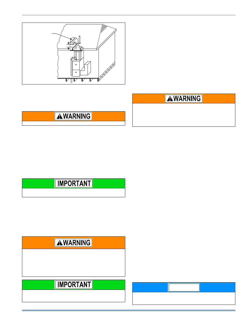
FIGURE 44: Attic and Crawl Space Combustion Air Termination
Be sure to instruct the owner not to block this intake pipe.
All electrical connections made in the field and in the factory should
be checked for proper tightness.
FIRE OR EXPLOSION HAZARD
Failure to follow the safety warnings exactly could result in serious
injury, death or property damage.
Never test for gas leaks with an open flame. Use a commercially
available soap solution made specifically for the detection of leaks
to check all connections. A fire or explosion may result causing
property damage, personal injury or loss of life.
Burner ignition may not be satisfactory on first startup due to resid-
ual air in the gas line or until gas manifold pressure is adjusted. The
ignition control will make three attempts to light before locking out.
12” Min.
12” minimum
between bottom
of air intake and
any material below.
HOT SURFACE IGNITION SYSTEM
Do not attempt to light this furnace by hand (with a match or
any other means). There may be a potential shock hazard from
the components of the hot surface ignition system. The fur-
nace can only be lit automatically by its hot surface ignition
system.
DO NOT set manifold pressure less than 3.2” w.c. or more than 3.8”
w.c. for natural gas at sea level. If manifold pressure is outside this
range, change main burner orifices.
NOTICE