0 feature specifications (see tables 6 and 7), Table 6. remote on/off, Table 7. feature specifications – KEPCO KFD 6-25-28W User Manual
Page 8: 0 output overvoltage clamp, 0 current limit, 0 remote on/off
4
KFD 62528W/060801
7.0 FEATURE SPECIFICATIONS (SEE TABLES 6 AND 7)
8.0 OUTPUT OVERVOLTAGE CLAMP
The KFD output voltage is controlled by the primary regulation loop. The control circuitry for the overvolt-
age clamp is independent of the KFD DC to DC Converter primary regulation loop. A secondary output
voltage control is provided by the overvoltage clamp circuitry, thereby reducing the possibility of output
overvoltage. This is realized by having the set point of the overvoltage clamp designed to be higher than
the set point of the primary loop.
9.0 CURRENT LIMIT
The KFD DC to DC Converter is protected against output overload by internal current limiting. This mode
of operation can be maintained for an unlimited time duration provided that the case temperature is main-
tained at or below 90°C. At the very point of current limit inception the DC to DC converter shifts from a
voltage control to a current control mode.
10.0 REMOTE ON/OFF
The DC to DC Converter can be remotely controlled via a switch (that the user must supply) across the
ON/OFF terminal and the -V
I terminal
(V
ON/OFF
). At logic low V
ON/OFF
=0 to 1.2 Volts, the unit is ON; and the
maximum I
ON/OFF
(when the module is ON) is 1 mA. The switch should be able to sink 1 mA when it is at a
logic low voltage. At logic high the maximum V
ON/OFF
of the KFD unit is 18 Volts. The maximum allowable
leakage current of the switch (at logic high) is then 50
µ
a.
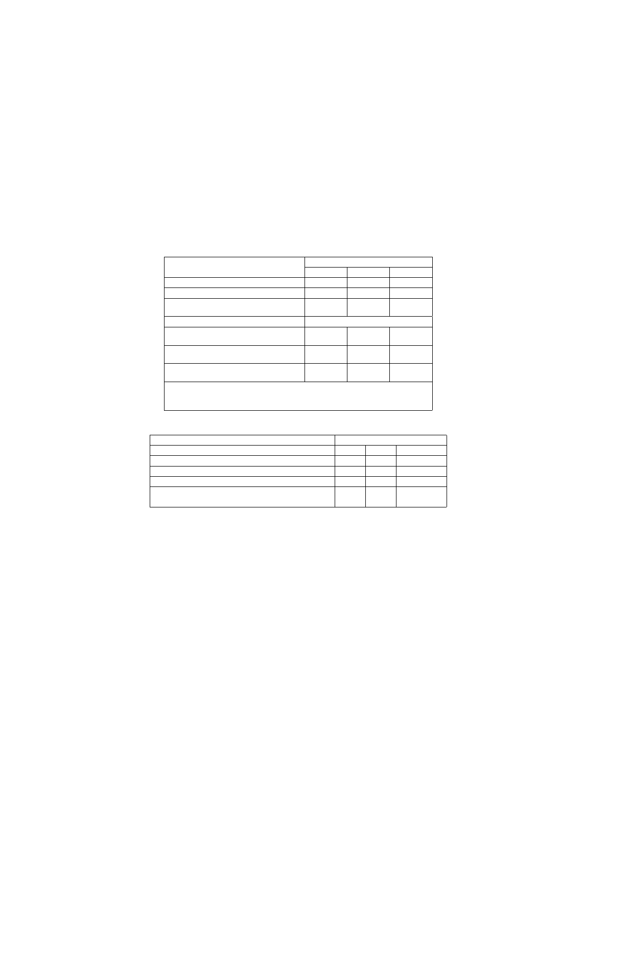
TABLE 6. REMOTE ON/OFF
State
Specification
Typ
Max
Unit
ON/.OFF CURRENT
Logic Low
1.0
ma
ON/OFF VOLTAGE
Logic Low
1.2
V
Logic High
ION/OFF=0
18
V
Open Collector Switch Specifications
Leakage Current During Logic High
(VON/OFF=18V)
50
µΑ
Output Low Voltage During Logic Low
ION/OFF =1mA
1.2
V
Turn On Time (Io =80%Iomax.; Vo within ±1%
of Vo,set)
5
10 ms
NOTES: 1. Remote On/Off (0 Volts <V1< 72 Volts, Open Collector Or Equivalent, Signal
Referenced to -V1 Terminal)
2. Logic Low-module ON; Logic High-module OFF
TABLE 7. FEATURE SPECIFICATIONS
Parameter
Specification
Typ
Max
Unit
Output Overvoltage Clamp, 6.6 Volts Minimum
7.0
8.0
V
Output Voltage Sense Range
1.0
V
Output Voltage Trim Range, 5.0 Volts Minimum
7.0
Parallel Operation Load Sharing
20%
Io,max,