Resistance and continuity measurement – Amprobe ACD-55HPQ Clamp-Meter User Manual
Page 17
ACD-55HPQ
4.3.4. Resistance and continuity measurement
WARNING
Before attempting any resistance measurement remove the power from the
circuit under test and discharge all the capacitors, if present.
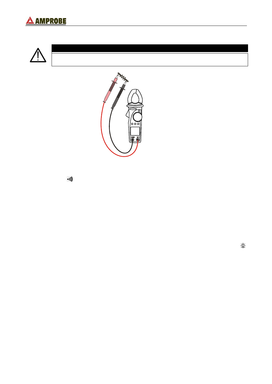
Fig. 8: resistance and continuity measurements
1. Select the “
Ω
” position.
2. Insert the red plug into V/
Ω jack and the black plug into COM one. For ease of use,
attach the rubber holster and insert a test lead (see Fig. 3).
3. Connect the test leads to the circuit under test (see Fig. 8). The measured resistance
value is displayed.
4. The buzzer emits a sound when the measured value is lower than 40
Ω.
5. The symbol "
O.L
" means that the measured voltage is higher than the full scale of the
instrument.
6. If the display is difficult to read, press D-H key to hold the measured value. To disable
this function press the D-H key again.
7. If the measurement is being performed in a dark environment, press and hold the
key for 1 second to activate the backlight. It automatically turns OFF after 5 seconds.
By pressing and holding the MAX/MIN/PK key for at least 1 second, the instrument
enables the maximum (MAX), minimum (MIN), average (AVG) and peak (PK)
measurement recording mode. All of these values are continually updated even if only one
is shown. Momentary MAX/MIN/PK key strokes will cycle the display through these
recorded values with their corresponding frequencies. To disable this function press and
hold pressed MAX/MIN/PK key at least for 1 second or turn the selector to any position.
EN - 13