Jumpers and connectors for the 9750 controller, See table 4 for jumper d, Table 4 for jumper description – Avago Technologies 3ware SAS 9750-4i User Manual
Page 25
Jumpers and Connectors for the 9750 Controller
www.lsi.com/channel/products
19
Jumpers and Connectors for the 9750
Controller
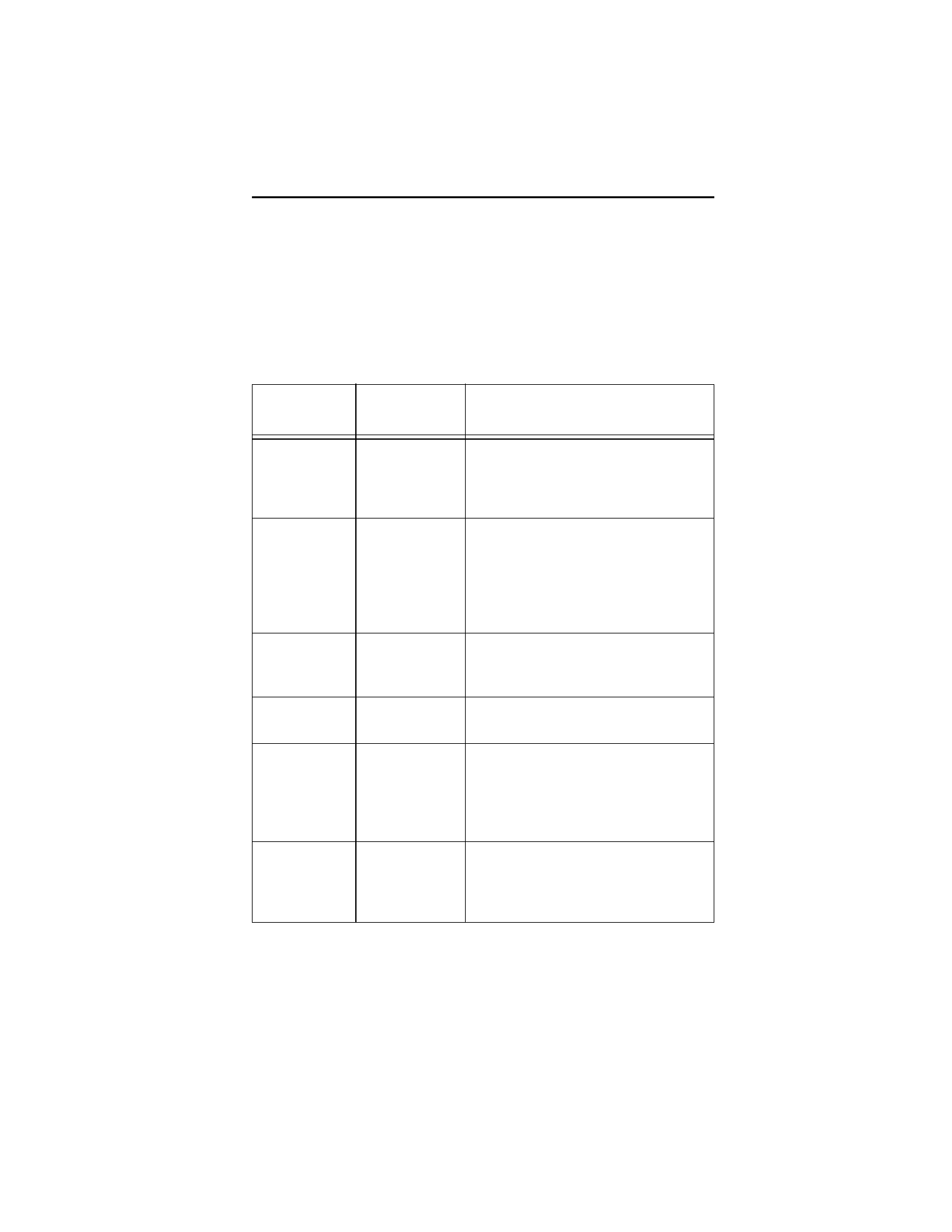
Table 4 describes the jumpers and connectors on the 9750 RAID
Controller Card. See Figure 1 for the 9750-4I controller card
layout. See Figure 2 for the 9750-8I controller card layout.
Table 4: Jumper and Connector Descriptions
Jumper/
Connector
Type
Description
JT3B1
Battery
Backup
Unit (BBU)
connector
20-pin connector
Connects the optional Intelligent
Battery Backup Unit (LSI iBBU07)
directly to the controller.
JT5A1
4 Lane
SATA+SAS
connector
Not available
on 9750-4I
Connects the cable from the
controller to SATA+SAS drive or
backplane.
Not available on 9750-4I
JT5B1
4 Lane
SATA+SAS
connector
Connects the cable from the
controller to SATA+SAS drive or
backplane.
JT5B2
Reserved for
LSI use only
4-pin connector
Reserved for LSI use only.
JT5B3
Set factory
defaults
connector
2-pin connector
Returns the board settings to the
defaults set in the factory.
Jumper should not be present during
normal operation.
JT6B1
Reserved for
LSI use only
2-pin connector
Jumper should not be present during
normal operation.
Reserved for LSI use only.