Capacitance – Avago Technologies LSI53C120 User Manual
Page 40
3-10
Specifications
provides the minimum and maximum values for these
LSI53C120 SCSI signals.
provides the minimum and maximum values for the
LSI53C120 Input signals.
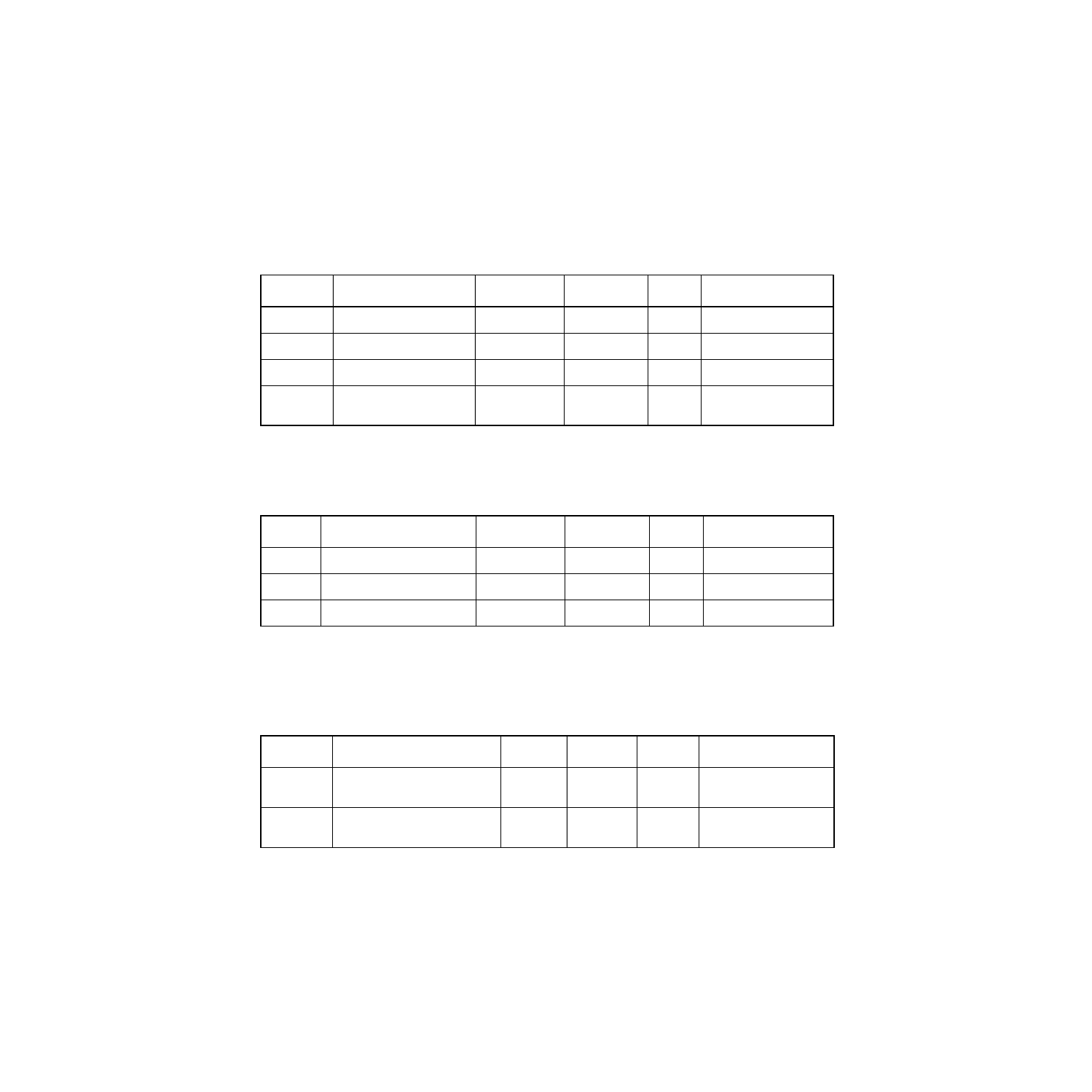
provides the minimum and maximum values concerning
capacitance for the LSI53C120.
Table 3.11
SCSI Signals – A_SMSG, A_SI_O/, A_SC_D/, A_SATN/, A_SBSY/, A_SSEL/,
A_SRST/, B_SMSG, B_SI_O/, B_SC_D/, B_SATN/, B_SBSY/, B_SSEL/,
B_SRST/
Symbol
Parameter
Min
Max
Unit
Test Conditions
V
IH
Input high voltage
1.9
V
DD
+ 0.5
V
–
V
IL
Input low voltage
V
SS
- 0.5
1.0
V
–
V
OL
Output low voltage
V
SS
0.5
V
48 mA
I
OZ
3-state leakage
(SRST/ only)
-10
-500
10
-50
µ
A
–
Table 3.12
Input Signals – CLOCK, DIFF_SENSE, DIFF_MODE/*, WS_ENABLE/*
Symbol
Parameter
Min
Max
Unit
Test Conditions
V
IH
Input high voltage
2.0
V
DD
+ 0.5
V
–
V
IL
Input low voltage
V
SS
- 0.5
0.8
V
–
I
IN
Input leakage
-10
1
10
µ
A
–
1. The minimum (I
IN
) Input leakage for DIFF_MODE/ and WS_ENABLE/ is -100
µ
A.
Table 3.13
Capacitance
Symbol
Parameter
Min
Max
Unit
Test Conditions
C
I
Input capacitance of input
pads
–
7
pF
–
C
IO
Input capacitance of I/O
pads
–
10
pF
–