PLANET VIP GW User Manual
Page 8
8
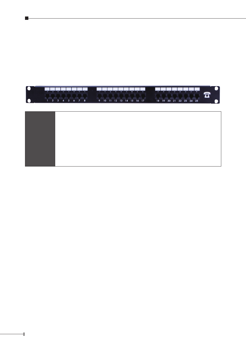
Connecting to the telephone patch panel (16-port/24-port model)
STEP 1: Attach the 25 port patch panel to the gateway through its RJ-21
connector.
STEP 2: The FXS LED indicators at telephone patch panel should be steady ON if
the RJ-21 connector is well connected to the gateway and the gateway is
powered on.
Note
The FXO interface is designed for connecting to PBXs (extension
line) or central office switches (CO line), and the FXS interface is
designed for connecting to analog telephone sets or fax machines.
If the telephone cable connects to VIP-16/2480 series, the FXS
interfaces are odd ports i.e. 1, 3, 5, 7, 9, 11, 13, 15, 17, 19, 21,
23, and the FXO interfaces are even ports, i.e. 2, 4, 6, 8, 10, 12,
14, 16, 18, 20, 22, 24.
Warning
Incorrectly connecting telephony devices to the RJ-11 port on the
Telephony Interface can cause permanent damage to the VoIP
Gateway
Administration Interface
PLANET VIP-GW provides GUI (Web based, Graphical User Interface) for machine
management and administration.