Cvp-705 assembly, Ab c d e, Kf g h j – Yamaha CVP-705B User Manual
Page 109
CVP-709/CVP-705 Owner’s Manual
109
CVP
-70
5 A
ssem
bl
y
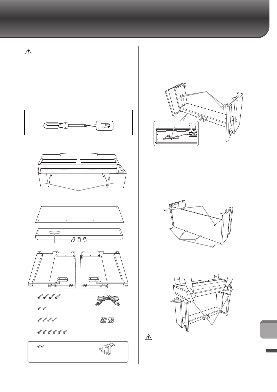
CVP-705 Assembly
CAUTION
• Assemble the unit on a hard and flat floor with ample space.
• Be careful not to confuse or misplace the parts, and be sure to
install all parts in the correct orientation. Please assemble the
unit in accordance with the sequence described here.
• Assembly should be carried out by at least two persons.
• Be sure to use only the included screws of the specified sizes.
Do not use any other screws. Use of incorrect screws can cause
damage or malfunction of the product.
• Be sure to tighten all screws upon completing assembly of each
unit.
• To disassemble the unit, reverse the assembly sequence.
Remove all parts from the package and make sure you have all
of the items.
1
Attach C to D and E.
Untie and straighten out the bundled pedal cord.
Do not discard the vinyl tie. You will need the vinyl tie later
in step 5.
Secure D and E to C using four screws F.
2
Attach B.
Align the holes on the upper side of B with the bracket holes
on D and E, then attach the upper corners of B to D and E
by finger-tightening two screws G.
Secure the bottom end of B using four screws H.
Securely tighten the screws G on the top of B that were
attached in step 2- .
3
Mount A.
Be sure to place your hands at least 15 cm from either end
of the main unit when positioning it.
CAUTION
• Be extra careful not to drop the unit or let your fingers be
pinched by the main unit.
• Do not hold the main unit in any position other than the position
specified here.
Have a Phillips-head (+) screwdriver of the appropriate size ready.
A
B
C
D
E
6 x 20 mm x 4
6 x 16 mm x 6
4 x 12 mm x 2
4 x 20 mm x 4
4 x 10 mm x 2
K
F
G
H
J
Remove foamed styrol pads from the package, position them on the
floor, then place A on top of them. Position the pads so that they will not
block the speaker box on the bottom of A.
Bundled pedal cord inside here.
Cord holders x 2
Headphone hanger
Power cord
D
D
C
E
E
F
B
E
D
H
G
A
Align the
screw holes.
15 cm or further in