Novation Bass Station II User Manual
Page 13
13
(e.g., if sustain is at maximum). Negative values invert the sense of the pitch variation; i.e.,
the pitch will fall during the attack phase of the envelope if Mod Env depth has a negative
setting.
Pulse Width
When the Oscillator waveform is set to Square/Pulse, the timbre of the “edgy” square wave
sound can be modified by varying the pulse width, or duty cycle, of the waveform.
The Pulse Width modulation source switch 18 allows the duty cycle to be varied either
manually or automatically. When set to Manual, the Pulse Width control 19 is enabled;
the parameter range is 5 to 95, where 50 corresponds to a square wave (a duty cycle
of 50%). Extreme clockwise and anticlockwise settings produce very narrow positive
or negative pulses, with the sound becoming thinner and more “reedy” as the control is
advanced.
Pulse width may also be modulated by either (or both) the Modulation Envelope or LFO 2,
by moving switch 18 to one of its other positions. The sonic effect of LFO modulation on
pulse width is very dependent on the LFO waveform and speed used, while using envelope
modulation can produce some good tonal effects, with the harmonic content of the note
changing over its duration.
Oscillator Sync
Oscillator Sync is a technique of using one oscillator (Osc 1 on Bass Station II) to add
additional harmonics to the waveform produced another (Osc 2), by making the waveform
from Osc 1 “retrigger” that of Osc 2 before a full cycle of Osc 2’s waveform has been
completed. This produces an interesting range of sonic effects, the nature of which
varies as the frequency of Osc 1 is altered, and is also dependent on the ratio of the two
oscillators’ frequencies, as the additional harmonics may or may not be musically related to
the fundamental frequency. The diagrams below illustrate the process.
OSC 2
OSC 1 (MASTER)
OSC 2 (SLAVE)
In general, it is advisable to turn down the volume of Osc 1 in the Mixer section 26 so that
you don’t hear its effect. Osc Sync is enabled by an On-Key function – Oscillator: Osc
1-2 sync (the higher D). The Sync 1-2 LED 20 illuminates when Osc 1-2 sync is selected.
The Sub Oscillator
In addition to the two primary oscillators, Bass Station II has a secondary “sub-octave”
oscillator, whose output can be added to that of Osc 1 and Osc 2 to create great bass
sounds. The sub oscillator’s frequency is always locked to that of Osc 1, so that the pitch is
either exactly one or two octaves below it, according to the setting of the Sub Oscillator
Octave switch 21 .
The waveform of the sub oscillator is selectable independently of Osc 1, with the Wave
switch 22 . The options are:
sinewave,
a narrow pulse wave or a
square wave.
Both the sub oscillator switches have associated sets of LEDs to confirm the current
setting. The sub oscillator output is fed to the Mixer Section where it may be added to the
synth sound to the degree required.
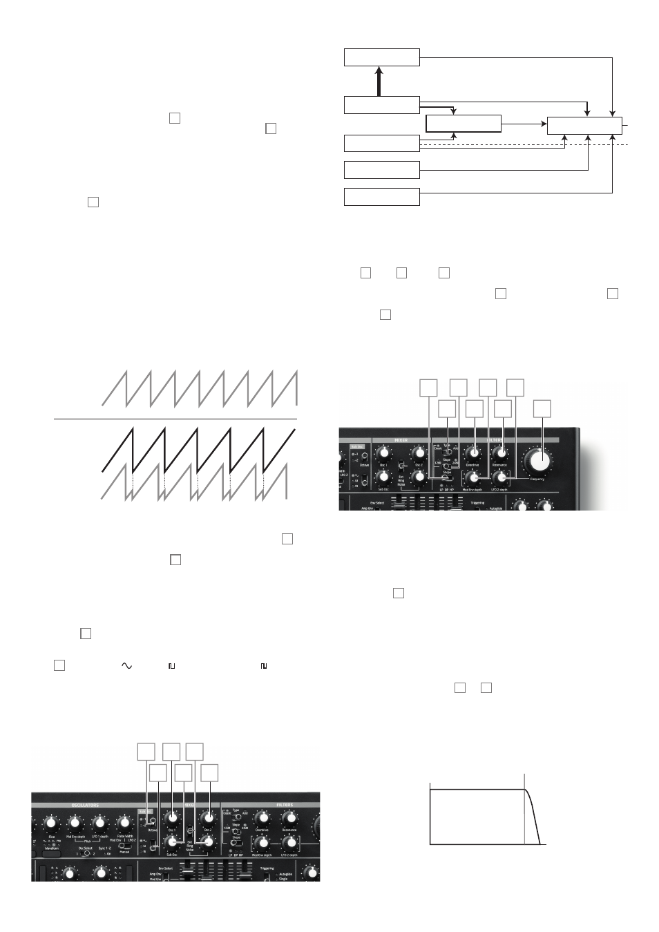
The Mixer Section
21
29
26
27
22 28
Oscillator 1
Ring Mod 1 * 2
Noise
External Input
Oscillator 2
Sub Oscillator
Sub Oscillator
Mixer
VCA
Mod Envelope
LFO 2
Filter
Overdrive
Distortion
Amp Envelope
Oscillator 1
Mod Envelope
LFO 1
LFO 2
pitch
pulse width
Oscillator 2
Mod Envelope
LFO 1
LFO 2
pitch
pulse width
Bass Station II Block diagram
Oscillator modulation controls
1. Audio flow
2. Mod flow
3. Sub Osc control from Osc 1
1. Mod flow
2. Sub Osc control from Osc 1
The outputs of the various sound sources can be mixed together in various proportions to
produce the overall synth sound, using what is essentially a standard 6-into-1 mono mixer.
The two Oscillators and the sub oscillator have dedicated, fixed level controls,
Osc 1 26 , Osc 2 27 and Sub 28 . The other three sources – the Noise source, Ring
Modulator output and external input - “share” a single level control, though any mix of the
three may be used. The Noise/Ring/Ext switch 30 assigns the fourth level control 29 to
one of these three sources at a time; having set the level in the mix for one of them, you can
move switch 30 to a different position and add that source to the mix without altering the
level of the first.
The Filter Section
31
35 37
32
33
36
34
30
The sum created in the mixer from the various signal sources is fed to the Filter Section.
Bass Station II’s filter section is both simple and traditional, and can be configured with
only a small number of single-function controls.
Filter type
The Type switch 31 selects one of two filter styles: Classic and Acid.
Acid configures the filter section as a fixed-slope, 4-pole (24 dB/oct), low-pass type. Low-
pass filters reject higher frequencies, so this filter setting will be suitable for many types of
bass sounds. This filter type is based on the simple diode-ladder designs that were found
in various analogue synths popular in the 1980s, and has a particular sonic character.
When the Acid filter is selected, the Slope and Shape switches are inoperative
When Type is set to Classic, the filter is configured as a variable type, whose Shape and
Slope may be set with the switches 32 and 33 respectively. A low-pass (LP), band-pass
(BP) or hi-pass (HP) characteristic may be selected with Shape; Slope sets the degree
of rejection applied to out-of-band frequencies; the 24 dB position gives a steeper slope
than the 12 dB; an out-of-band frequency will be attenuated more severely with the steeper
setting.
Volume
Volume
Frequency
Volume
Volume
Frequency
Cutoff
Frequency
Cutoff
Frequency
Cutoff
Frequency
Cutoff
Frequency
Frequency
Frequency
Cutoff
Frequency
Cutoff
Frequency
Cutoff
Frequency
Cutoff
Frequency
Volume
Volume
Frequency
Volume
Volume
Frequency
Frequency
Frequency
Low Pass 24 dB (Classic / Acid)