Quick start – Samson Concert 288m Presentation Dual-Channel Wireless Lavalier & Headset Microphone System (D: 542 to 566 MHz) User Manual
Page 11
Concert 288m Dual Wireless
11
Quick Start
1.
Physically place the AR299m receiver
where it will be used, and extend the
antennas vertically. The general rule
of thumb is to maintain “line of sight”
between the receiver and transmitter
so that the person using or wearing the
transmitter can see the receiver.
2.
With the AR299m powered off, connect
the included power adapter.
3.
With your amplifier or mixer off and
volume control all the way down, connect
the AR299m receiver output jack to the
mic or line level input of the mixer or
amplifier using the balanced Channel
1 XLR output or (CH1/CH2 mixed)
unbalanced 1/4” or 1/8” line level
outputs. Turn the VOLUME 1 knob on the
AR299m clockwise to turn its power on,
but keep the level low.
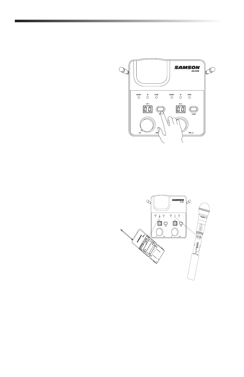
4.
Press the CH 1 SCAN button for more
than 2 seconds (the display will start
to flash quickly) on the front of the
AR299m receiver to scan for an available
channel. Once the optimal channel is
selected the receiver will enter IR Set
mode. The display will flash slowly
in IR Set mode. If you want to set a
transmitter to the receiver’s currently
selected channel, press and hold the
SET button for more than 10 seconds
(until the display flashes slowly) to enter
IR Set mode directly. (figure 1).
5.
With transmitter POWER set to “on”
position the CH88 or CB88 transmitter
about 6-12” (15-30 cm) from the front
of the AR299m with the transmitter’s
battery door open and IR window facing
the IR transmitter on the front panel of
the AR299m receiver (figure 2).
6.
When the transmission of the operating
channel is complete, the AR299m
will receive RF signal and the READY
indicator will light green indicating that
it is receiving wireless signal from the
transmitter.
7.
Repeat steps 4-6 to set up the other transmitter for CH 2 of AR299m. NOTE: depending
on your application you can use either the balanced Channel 2 XLR output or the mixed
unbalanced output (1/4” or 1/8”).
Figure 1
Figure 2