2 back panel, Back panel – Bosch PLE-1ME240-US Plena Mixer Amplifier User Manual
Page 13
Plena Mixer Amplifier
System Overview | en
13
Bosch Security Systems B.V.
Installation and Operation manual
PLE-1MExx0-xx | V1.0 | 2011.04
3.4.2
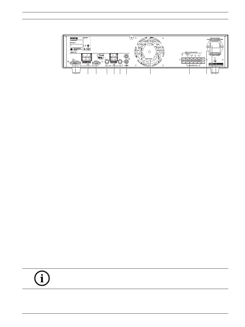
Back panel
Figure 3.2
Back panel
Number
Description
1
Microphone/line 1 input with trigger, Euro style screw terminal connector -
DIP switch settings for: chime, PTT (push to talk), mic./line, speech filter,
and phantom power (see number 2)
2
DIP switch for microphone/line 1 and microphone/line 2 (see numbers 1
and 3 respectively)
3
Microphone/line 2 input, Euro style screw terminal - DIP switch settings for
speech filter, mic./line, and phantom power (see number 2)
4
Microphone/line 3 input, 6.3 mm - 1/4" jack connector - DIP switch settings
for mic./line, and phantom power (see number 5)
5
DIP switch for microphone/line 3 and microphone/line 4 (see numbers 4
and 6 respectively)
6
Microphone/line 4 input, 6.3 mm - 1/4" jack connector - DIP switch settings
for mic./line, and phantom power (see number 5)
7
Music input, 2x RCA/cinch connectors, Stereo, summed mono
8
Cooling fan (PLE-1ME120 & PLE-1ME240)
9
Outputs:
–
Call only, screw terminal connector 100 V
–
Screw terminal connector 100 V, and 4 Ohm
10
Mains fuse
11
Earth connection screw
12
Mains connector (3-pole)
12
11
10
9
8
7
6
4
3
5
2
1
NOTICE!
The unit must be earthed.
Always allow adequate space at the rear of the unit for ventilation.